


Instruction Manual
D101351X012
646 Transducer
January 2015
9
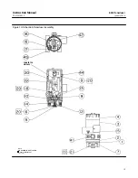
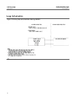
Figure 3. Dimensions and Connections
35
(1.38)
6.4
(.25)
127.0
(5.00)
72.8
(2.86
)
102.1
(4.02
)
152.4
(6.00)
152.4
(6.00)
79.2
(3.12)
47.8
(1.88)
127.0
(5.00)
9.5
(.38)
9.7
(0.38)
mm
(INCH)
CENTERLINE
OF ACTUATOR
EXHAUST
1/4‐18 NPT
OPTIONAL OUTPUT
OR GAUGE CONN
1/4‐18 NPT
OUTPUT CONN
1/2‐14 NPT
CONDUIT CONN
OPTIONAL
GAUGE
67CFR
1/4‐18 NPT
SUPPLY
CONN
CAP
REMOVAL
CLEARANCE
57
(2.25)
106.4
(4.19)
62.0
(2.44)
38B3958‐A
A6816‐1 / IL
41.1
(1.62)
Pneumatic Connections
As shown in figure 3, all pressure connections on the transducer are 1/4 NPT internal connections. Use 10 mm
(3/8‐inch) tubing for all pressure connections. Refer to the vent subsection below for remote vent connections.
Supply Pressure Requirements
WARNING
Severe personal injury or property damage may occur if the instrument air supply is not clean, dry and oil‐free. While use
and regular maintenance of a filter that removes particles larger than 40 micrometers in diameter will suffice in most
applications, check with an Emerson Process Management field office and industry instrument air quality standards for use
with corrosive air or if you are unsure about the proper amount or method of air filtration or filter maintenance.
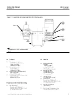
Supply pressure must be clean, dry air. Use a Fisher 67CFR filter regulator with standard 5 micrometer filter, or
equivalent, to filter and regulate supply air. The filter regulator can be mounted on a bracket with the transducer as
shown in figure 11 or mounted on the actuator mounting boss. An output pressure gauge may be installed on the
regulator to indicate the supply pressure to the transducer. Also, as an aid for calibration, a second gauge may be
installed on the transducer to indicate transducer output pressure.