


Instruction Manual
D103425X012
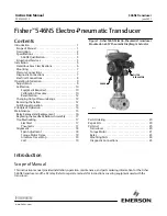
546NS Transducer
June 2021
11
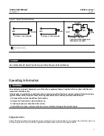
1. Check the supply pressure to ensure it agrees with the minimum pressure on the transducer nameplate.
2. Adjust the input current to 4.00 mA DC.
3. Turn the zero screw until the output pressure is 0.2
±
0.006 bar (3.00
±
0.09 psig).
4. Adjust the input to 20.00 mA DC.
5. If the output pressure is less than 1.028 bar (14.91 psig), turn the span screw clockwise to increase the span. If the
output pressure is greater than 1.040 bar (15.09 psig), turn the span screw counterclockwise to decrease the span.
Note
Do not watch the output gauge while turning the span screw because the change in output is not a good indication of the change
in span. While turning the span adjustment screw, the output pressure may move in the opposite direction than expected. For
example, while turning the span screw in the INCREASING SPAN direction, the output pressure might decrease.
This should be disregarded since even though the output pressure decreases, the output span is increasing.
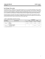
6. Repeat steps 2 through 5 until the output pressure is within one‐third of the accuracy limits at 4 and 20 mA DC.
One‐third of the accuracy limits for a 0.2 to 1.0 bar (3 to 15 psig) output range is 1/3
(
±
0.0075)
(15.00 - 3.00) =
±
2 mbar (
±
0.03 psig). Calibrate for maximum accuracy at the target end points [0.20 and 1.00 bar (3.00 and 15.00
psig)]. This allows for error at other calibration points in between.
7. Run the transducer through three calibration cycles before recording data. The cycles should be run from exactly
4.00 to 20.00 mA DC in a slow ramping fashion (no large step inputs).
Note
Large step inputs during calibration can result in an inaccurate reflection of the actual state of calibration. Use care to always
change input in a slow, ramping fashion.
8. After returning from 20.00 mA DC during the last exercise cycle, move back upscale to the midpoint (12.00 mA DC)
and record the first data point. Table 5 is an example of recorded data.
9. Record at the other calibration points desired by moving upscale to 20.00 mA DC then down scale to 4.00 mA DC,
then back upscale to 12.00 mA DC. Refer to table 5 for common calibration points.
CAUTION
Reversing the DC input during the calibration cycle may result in product damage.
Note
During the calibration cycle, use care to avoid overshoot. In other words, if data is to be recorded at an 8.00 mA DC input while
moving upscale and you accidently pass 8.00 to some higher value, run the test again starting at step 7. with the three exercise
cycles.
Do not
reverse direction and move down scale to 8.00 mA DC.
10. After completing the calibration cycle and recording data, verify that all data is within
±
0.75% accuracy limits. If not,
the transducer may need to be recalibrated to move the end points slightly to bring the entire calibration curve
within the accuracy limits.


