manualshive.com logo in svg
background image

www.Fisher.com

Fisher

R

 4200 Electronic Position Transmitters

Contents

Introduction

2

. . . . . . . . . . . . . . . . . . . . . . . . . . . . . . . . .

Scope of Manual

2

. . . . . . . . . . . . . . . . . . . . . . . . . . . . .

Description

2

. . . . . . . . . . . . . . . . . . . . . . . . . . . . . . . . .

Specifications

5

. . . . . . . . . . . . . . . . . . . . . . . . . . . . . . .

Educational Services

5

. . . . . . . . . . . . . . . . . . . . . . . . .

Installation

5

. . . . . . . . . . . . . . . . . . . . . . . . . . . . . . . . . .

Special Instructions for “Safe Use” and 

Installations in Hazardous Locations

6

. . . . . . . . . .

CSA

7

. . . . . . . . . . . . . . . . . . . . . . . . . . . . . . . . . . . .

FM

7

. . . . . . . . . . . . . . . . . . . . . . . . . . . . . . . . . . . . .

ATEX

8

. . . . . . . . . . . . . . . . . . . . . . . . . . . . . . . . . . .

Mechanical Connections

8

. . . . . . . . . . . . . . . . . . . . . .

Sliding‐Stem Actuator Mounting

8

. . . . . . . . . . .

Rotary‐Shaft Actuator Mounting

9

. . . . . . . . . . . .

Long‐Stroke Sliding‐Stem Actuator

Mounting Fisher 585C and 470‐16

10

. . . . . . .

Long‐Stroke Sliding‐Stem Actuator

Mounting Fisher 585CLS and 490

11

. . . . . . . .

Electrical Connections

12

. . . . . . . . . . . . . . . . . . . . . . .

Conduit

12

. . . . . . . . . . . . . . . . . . . . . . . . . . . . . . .

Field Wiring

12

. . . . . . . . . . . . . . . . . . . . . . . . . . . .

Potentiometer Alignment

14

. . . . . . . . . . . . . . . . . . . .

Direct or Reverse Action

16

. . . . . . . . . . . . . . . . . . . . .

Operating Information

16

. . . . . . . . . . . . . . . . . . . . . . . .

Initial Considerations

16

. . . . . . . . . . . . . . . . . . . . . . . .

Transmitter and Position Switch 

Conditions

17

. . . . . . . . . . . . . . . . . . . . . . . . . .

Normal Operation

17

. . . . . . . . . . . . . . . . . . . . . . . . . .

Calibration

18

. . . . . . . . . . . . . . . . . . . . . . . . . . . . . . . . . .

Test Equipment Required

20

. . . . . . . . . . . . . . . . . . . .

Test Connections to the Field Wiring

Compartment

21

. . . . . . . . . . . . . . . . . . . . . . . . . . .

Transmitter Circuit Zero and Span

Adjustment

22

. . . . . . . . . . . . . . . . . . . . . . . . . . . . .

High and Low Position Switch Adjustment

22

. . . . . .

Setting the High Position Switch

23

. . . . . . . . . . .

Setting the High Position Switch

Deadband

23

. . . . . . . . . . . . . . . . . . . . . . . . . . .

Setting the Low Position Switch

23

. . . . . . . . . . .

Setting the Low Position Switch 

Deadband

24

. . . . . . . . . . . . . . . . . . . . . . . . . . .

Position Switch Circuit Shutoff

24

. . . . . . . . . . . . . . . .

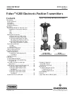
Figure 1. Typical Fisher 4200 Position Transmitters

W4273‐1

SLIDING‐STEM

ACTUATOR MOUNTING

W4274‐1

ROTARY

ACTUATOR MOUNTING

Principle of Operation

24

. . . . . . . . . . . . . . . . . . . . . . . .

Transmitter Circuit

25

. . . . . . . . . . . . . . . . . . . . . . . . . .

Position Switch Circuit

26

. . . . . . . . . . . . . . . . . . . . . . .

Maintenance

26

. . . . . . . . . . . . . . . . . . . . . . . . . . . . . . . .

Troubleshooting Procedures

27

. . . . . . . . . . . . . . . . .

Transmitter Circuit

27

. . . . . . . . . . . . . . . . . . . . . .

Position Switch Circuit

28

. . . . . . . . . . . . . . . . . . .

Parts Ordering

32

. . . . . . . . . . . . . . . . . . . . . . . . . . . . . . .

Parts List

33

. . . . . . . . . . . . . . . . . . . . . . . . . . . . . . . . . . .

Loop Schematics and Nameplates

45

. . . . . . . . . . . . . .

Instruction Manual

D200354X012

4200 Transmitters

March 2011

Содержание Fisher 4200

Страница 1: ...mitter and Position Switch Conditions 17 Normal Operation 17 Calibration 18 Test Equipment Required 20 Test Connections to the Field Wiring Compartment 21 Transmitter Circuit Zero and Span Adjustment 22 High and Low Position Switch Adjustment 22 Setting the High Position Switch 23 Setting the High Position Switch Deadband 23 Setting the Low Position Switch 23 Setting the Low Position Switch Deadba...

Страница 2: ...process control system or programmable logic controller 4200 transmitters are available as a transmitter only as a transmitter with integral high and low position switches or with high and low position switches only Refer to the nameplate to determine the type of transmitter Use the Type number and table 2 to determine the output and travel ranges available from the transmitter When the instrument...

Страница 3: ...y and deadband Repeatability 0 25 of span Operating Influences Ambient Temperature For a 56_C 100_F change in normal operating conditions maximum zero shift is 0 5 maximum span shift is 0 75 of span Power Supply Output signal changes less than 0 1 when operating terminal voltage varies between 11 and 30 volts DC Electromagnetic Compatibility for 4211 and 4221 Meets EN 61326 1 First Edition Immunit...

Страница 4: ...o 4 125 0 670 4 125 4220 4221 4222 0 to 884 150 884 12 Inch Transducer 0 to 305 105 305 0 to 12 4 125 12 24 Inch Transducer 0 to 610 305 610 0 to 24 12 24 1 Zero position is the range of values over which the transmitter zero can be adjusted Span is the range of shaft rotation or stem travel the transmitter span can be adjusted For example a zero position of 45 degrees and a span of 15 degrees mea...

Страница 5: ...n be set at any point of travel The low relay position switch can be offset from the high relay position switch trip point by as little as 1 20 of the travel In the event of a power loss both position switch relays de energize indicating loss of transmitter power Specifications Specifications for the 4200 transmitters are listed in table 1 WARNING This product is intended for a specific current ra...

Страница 6: ...otentiometer that senses position Remove the cover on the transmitter compartment to gain access to this compartment The transmitter compartment is adjacent to the symbol on the housing Except for a 4211 or 4221 transmitter the field wiring compartment contains a printed wiring board with the terminal blocks figure 4 for connecting field wiring and associated cable assemblies It also contains the ...

Страница 7: ... 4220 4221 4222 Class II Division 1 GP E F G T5 T5 Tamb v 71 C 4X FM Special Conditions of Safe Use Intrinsically Safe Explosion proof Dust Ignition proof Non Incendive No special conditions for safe use Refer to table 6 for approval information figure 25 for the FM loop schematic and figure 26 for CSA and FM approval nameplates Table 6 Hazardous Area Classifications FM United States Certification...

Страница 8: ...igure 27 for ATEX approval nameplates Type n Dust No special conditions for safe use Refer to table 7 for approval information and figure 27 for ATEX approval nameplates Table 7 Hazardous Area Classifications ATEX Certificate Type Certification Obtained Entity Rating Temperature Code Enclosure Rating ATEX 4211 4221 II 1 G D Intrinsically Safe Gas Ex ia IIC T4 T5 Ui 30 VDC Ii 150 mA Pi 1 0 W Ci 5 n...

Страница 9: ...y move the lever assembly key 30 until its center line is parallel with the center line of the operating arm key 25 12 Tighten the two cap screws key 37 in the slotted holes 13 Stroke the actuator to ensure that full travel is allowed 14 Perform the electrical connection and direct and reverse action procedures 15 Verify potentiometer alignment by performing the potentiometer alignment procedure R...

Страница 10: ...d the actuator CAUTION Free release of the cable key 100B will damage the transducer Whenever the cable key 100B is extended take steps to ensure that free release does not happen 6 Carefully pull the cable key 100B down to the cable bracket key 60 and attach it with the socket head cap screw key 102 the lock washer key 83 and the nut key 72 7 Remove the four cap screws key 100D and the mounting p...

Страница 11: ...e spacers key 101 between the mounting plate key 63 and the actuator CAUTION Free release of the cable key 100B will damage the transducer Whenever the cable key 100B is extended take steps to ensure that free release does not happen 6 Carefully pull the cable key 100B down to the cable clip key 61 and attach it with the socket head cap screw key 102 the lock washer key 83 and the nut key 72 7 Rem...

Страница 12: ... field wiring compartment The transmitter is powered by 24 volts DC Refer to table 1 to determine the power supply requirements For units without position switches the 24 volts DC can be provided by the receiving device or an external supply For units with position switches the power supply provides 24 volt DC power to the position switch circuit in units without the transmitter or to both the pos...

Страница 13: ...CONNECTED EVEN IF RELAY OUTPUTS ARE NOT USED 1 4 1 1 2 2 2 3 4 3 3 POWER SUPPLY DEVICE RECEIVING 4 TO 20 MA DC SIGNAL DEVICE RECEIVING LO POSITION SWITCH OUTPUT CONTACT CLOSURE DEVICE RECEIVING HI POSITION SWITCH OUTPUT CONTACT CLOSURE TRANSMITTER FIELD WIRING FOR FISHER 4210 4215 OR 4220 TRANSMITTER WITH POSITION SWITCHES AND 4212 OR 4222 POSITION SWITCHES WITHOUT THE TRANSMITTER RELAY RETURN POW...

Страница 14: ... transmitter without position switches Connect a wire from the terminal of the power supply to the terminal on the barrier strip key 11 Connect a wire from the terminal of the power supply to the negative terminal of the receiving device Connect a wire from the receiving device positive terminal to the terminal on the barrier strip 4 Connect the grounding terminal key 58 to an earth ground 5 For a...

Страница 15: ...LABEL 1 Remove power from the instrument 2 Connect the digital voltmeter DVM leads as follows a For all transmitters except a 4212 or 4222 connect between TP3 and TP4 on the printed wiring board b For a 4212 or 4222 transmitter connect the DVM between TP5 and TP6 3 Loosen the appropriate set screw connecting the potentiometer shaft to the linkage a For sliding stem applications loosen the set scre...

Страница 16: ...ion Direct action means when looking at the slotted end of the potentiometer shaft a clockwise rotation of the shaft produces an increasing output signal from the transmitter Reverse action means when looking at the slotted end of the potentiometer shaft a clockwise rotation of the shaft produces a decreasing output signal from the transmitter The transmitter produces a direct or reverse action ou...

Страница 17: ... difference between trip and reset points of a relay D A 4215 transmitter obtains position information from a dual potentiometer on the same shaft which allows for individual potentiometers for the transmitter circuit and the position switch circuits The transmitter input is from one of the potentiometers and its output connects to TB3 figure 6 mounted on the field circuit printed wiring board The...

Страница 18: ...MINALS BARRIER STRIP KEY 11 NOTE WIRES CONNECTED TO TB1 ARE SHOWN IN THE COLOR SEQUENCE FOR DIRECT ACTION FOR REVERSE ACTION THE COLOR SEQUENCE IS RED ORANGE AND BROWN FROM LEFT TO RIGHT 1 END VIEW CUTAWAY SIDE VIEW END VIEW FOR FISHER 4210 4215 OR 4220 TRANSMITTER WITH POSITION SWITCHES AND 4212 OR 4222 POSITION SWITCHES WITHOUT THE TRANSMITTER FOR FISHER 4211 OR 4221 TRANSMITTER WITHOUT POSITION...

Страница 19: ...ut position switch circuits refer to the transmitter circuit zero and span adjustment procedures in this section If satisfactory results cannot be obtained during calibration refer to the appropriate procedures in the Maintenance section Figure 7 Transmitter and Position Switch Conditions also see table 8 ACTUATOR TRAVEL UP OR DOWN REFER TO TABLE 8 FOR CONDITIONS ACTUATOR TRAVEL UP OR DOWN TERMINA...

Страница 20: ...rse A D Down CW 4 Hi Up CCW 20 Lo B C Up CW 4 Hi Down CCW 20 Lo 4211 Not required for transmitter without position switches FOR SLIDING STEM ACTUATORS 4210 4220 Direct Down CW 20 Hi Up CCW 4 Lo Reverse Up CCW 20 Hi Down CW 4 Lo 4212 4222 Direct Down CW N A Hi Up CCW N A Lo Reverse Not available for position switches without transmitter 4215 Direct Down CW 20 Hi Up CCW 4 Lo Reverse Down CW 20 Hi Up...

Страница 21: ...ches the R terminal on TB3 must be connected to the power supply negative terminal for proper instrument operation even if the position switch outputs are not used For a 4211 or 4221 transmitter without position switches use a two wire system with the indicating device installed as shown in figure 8 Figure 8 Calibration and Bench Check Test Setup NOTES CONNECT DVM TO TEST POINTS AS DIRECTED BY CAL...

Страница 22: ... Installation section 8 Stroke the valve or device to the point of travel where the transmitter output is to be 4 milliamperes DC 9 Adjust the zero potentiometer R1 figure 5 until the output is 4 milliamperes DC 1 00 volt across 250 ohms 10 Stroke the valve or device to the point of travel where the transmitter output is to be 20 milliamperes DC 11 Adjust the span potentiometer R2 figure 5 until t...

Страница 23: ...y counterclockwise Note The potentiometers are 25 turn trimpots with a slip clutch To set these potentiometers at their maximum counterclockwise position turn them 25 or more turns in the counterclockwise direction Setting the High Position Switch For 4210 4220 4212 4222 and 4215 direct acting transmitters refer to figure 5 for location of adjustments 1 Turn the high position switch potentiometer ...

Страница 24: ...wer from the instrument and disconnect the ohmmeter 5 Perform the installation and or operating procedures to place the transmitter in service and replace the transmitter covers Position Switch Circuit Shutoff Refer to figure 5 for location of adjustments Certain conditions may require the position switch circuit capabilities to be shut off To shut off the position switches turn the high position ...

Страница 25: ...ompared to the settings of the high and low position switch set points and provides an on or off condition for the relays Instruments that use a single element potentiometer use the same element for both the transmitter input and the input to the position switch circuits A 4215 transmitter with dual element potentiometers uses one element of the potentiometer for the transmitter input and the othe...

Страница 26: ...ate position switch relay K1 or K2 figure 10 when travel reaches the trip points established by the adjustments The 4215 transmitter uses dual potentiometers which allows individual potentiometers for the transmitter circuit and the position switch circuit Figure 10 Schematic Diagram for the Field Printed Wiring Board NOTE RELAYS K1 AND K2 ARE SHOWN IN THE DE ENERGIZED POSITION TRIPPED POSITION 29...

Страница 27: ...ectrical power before removing the instrument covers in a hazardous area Personal injury or property damage may result from fire and explosion if power is applied to the instrument with the covers removed in a hazardous area Test equipment for the following procedure is listed in the Calibration section Voltage references in this procedure may vary depending on the temperature of the instrument Th...

Страница 28: ...on perform the potentiometer alignment If the problem remains replace the pot bushing assembly key 3 figure 11 or 14 b If the potentiometer wiper voltage checks good but the transmitter output is constant or non linear the problem may be due to improper potentiometer alignment Perform the potentiometer alignment procedures then repeat step 8 above c If the potentiometer voltage is present but the ...

Страница 29: ...itter 49A7893 M IL APPLY LUBRICANT OR SEALANT NOTE ON 4212 4222 USE KEY 35 INSTEAD OF KEY 19 AT THE FEEDTHROUGH POSITION OMIT KEY 10 1 1 68 1 Transmitter Printed Wiring Board Refer to figure 12 for component locations Removal 1 Remove power from the transmitter 2 With the transmitter compartment covers removed disconnect the connectors from J1 J2 and J3 if they are used 3 Note the locations of the...

Страница 30: ...Dual Pot GE15866X042 W3 W4 W5 W6 See figure 5 for jumper locations on the printed wiring board NOTES 1 The three wire cable assembly connected to J3 provides the position switch circuit output to relays K1 and K2 on the field circuit printed wiring board 2 Terminal block number 1 TB1 provides the connections for the three wire cable assembly from the potentiometer On a dual potentiometer system it...

Страница 31: ... replacement Replacement 1 When the replacement board is ready lower the board into the transmitter compartment 2 Insert and tighten the three screws and install the wiring connections that were removed 3 The red and black power wires must be connected to TB3 according to the transmitter type Pot Bushing Assembly Replacement CAUTION Remove the wiring assembly or assemblies connected between the po...

Страница 32: ...onding with your Emerson Process Management sales office about this equipment always mention the transmitter serial number When ordering replacement parts refer to the part number of each required part as found in the following parts lists WARNING Use only genuine Fisher replacement parts Components that are not supplied by Emerson Process Management should not under any circumstances be used in a...

Страница 33: ...Key Description Part Number 9 Wire red 18 AWG 50 8 mm 2 inches 4211 4221 146 mm 5 75 inches 4210 4220 4215 4212 and 4222 10 Wire black 18 AWG Not used on 4212 4222 50 8 mm 2 inches 4211 4221 146 mm 5 75 inches 4210 4220 4215 11 Barrier Strip 4211 4221 only plastic 12 Machine Screw 4211 4221 only stainless steel 2 req d 13 Barrier Marker Strip 4211 4221 only 14 O Ring nitrile 2 req d T1205106562 15...

Страница 34: ...eq d Key Description 33 Stem Bracket zn pl steel Size 30 thru 130 with 54 mm 2 125 inch max travel Size 80 thru 130 w 54 thru 105 mm 2 125 thru 4 125 inch max travel 34 Stem Mounting Bracket zn pl steel Size 30 40 45 63 64 Size 46 60 68 80 86 130 Size 100 35 Cap Screw zn pl steel 2 req d Size 30 45 Size 40 Size 64 Size 68 80 Size 100 36 Sleeve acetal 37 Cap Screw steel 2 req d 38 Stem Washer 2 req...

Страница 35: ...NECTION PICKUP PIN CONNECTION NUMBER 2 PICKUP PIN CONNECTION NUMBER 1 TRAVEL mm Inch Up to 54 2 125 max Up to 105 4 125 max PICK UP PIN CONNECTION NUMBER 1 2 2 1 2 2 2 1 Key Description 36 Sleeve acetal 37 Cap Screw steel 2 req d 38 Stem Washer 2 req d Size 40 45 pl steel Size 60 64 zn pl steel 39 Stem Spacer steel 2 req d Size 40 64 Size 45 48 Lithium grease not furnished with transmitter 49 Thre...

Страница 36: ...Size 45 46 50 60 w 3582 3590 DVC5010 Size 70 w or w o 3582 3590 Size 70 87 w MO w 3582 up to 3 inch travel Size 80 87 w o positioner Size 80 w 3582 3590 DVC5010 Size 70 thru 87 w MO w DVC5010 up to 76 mm 3 inch travel Size 70 w MO w DVC5010 102 mm 4 inch travel Size 100 Key Description Hex nut not shown Size 30 34 40 w 3582 3590 DVC5010 4 req d Size 45 46 50 60 w 3582 3590 DVC5010 4 req d Size 70 ...

Страница 37: ...T 4 INDENT MARK INDENT MARK INDENT 1 INDENT 2 INDENT 3 INDENT 4 INDENT 5 INDENT 6 INDENT 7 INDENT 8 STEM BRACKET VIEW STEM BRACKET VIEW FOR SIZES 25 AND 50 FOR SIZES 100 39A7636 D DOC 40B9854 D DOC TRAVEL mm INCHES 1 2 3 4 5 6 7 8 19 29 38 51 64 76 89 102 0 75 1 125 1 5 2 2 5 3 3 5 4 INDENT NUMBER TRAVEL mm INCHES 1 2 3 4 19 29 38 51 0 75 1 125 1 5 2 INDENT NUMBER ...

Страница 38: ...Operating Arm pl steel 26 Cap Screw pl steel 27 Square Nut pl steel 29 Torsional Spring zn pl steel 30 Lever Assembly Size 100 w 0 75 thru 2 125 inch travel Size 100 w 2 5 thru 4 inch travel Key Description Note The lever assembly key 30 is not used with size 25 and 50 actuators Individual parts below key 30A through 30C are needed 30A Lever Bearing Assembly 30B Transfer Pin stainless steel 30C Pi...

Страница 39: ...Torsional Spring zn pl steel 30A Lever Bearing Assembly steel 30B Transfer Pin stainless steel 30C Pickup Pin stainless steel 31 Shoulder Screw stainless steel Key Description 32 Hex Cap Screw pl steel 2 req d 33 Stem Bracket steel Size 225 450 Size 675 36 Sleeve acetal 49 Thread Locking Adhesive medium strength not furnished with transmitter 51 Thread Locking Adhesive mild strength not furnished ...

Страница 40: ... linkage 1051 1052 Size 33 1051 1052 Size 30 thru 70 and 1061 Size 30 thru 68 1061 Size 80 and 100 Key Description 21 Mounting Plate steel continued w tandem linkage 1051 1052 Size 30 40 and 1061 Size 30 1051 1052 Size 60 70 and 1061 Size 40 thru 68 32 Cap Screw pl steel 2 req d 50 Anti seize lubricant not furnished with transmitter 52 Coupler stainless steel 1051 1052 1061 all sizes except 33 105...

Страница 41: ...el 54 Coupling aluminum 57 Coupling Plate Assembly Figure 21 Typical Transmitter Mounting on Fisher 1063 1064 1065 1066 or 1066SR Actuator 34A8841 A DOC APPLY LUBRICANT Parts for Mounting the Transmitter on 1063 1064 1065 1066 or 1066R Actuator without Tandem Linkage figure 21 Key Description 21 Mounting Plate steel 1063 1066 Size 20 27 and 1064 1065 Size 20 1063 1064 1065 1066 Size 75 32 Cap Scre...

Страница 42: ...ual D200354X012 4200 Transmitters March 2011 42 Figure 22 Typical Transmitter Mounting on a Fisher 585C with Travel Greater than 4 inches 470 16 Actuator SECTION A A GE16564 A A TRANSDUCER ASSEMBLY 81 64 82 GE13433 32 ...

Страница 43: ...5H Cylinder size 305 356 mm 12 14 inches Max travel 305 mm 12 inches and 406 mm 16 inches Yoke Boss 7 IN Cylinder size 127 to 356 mm 5 to14 inches Max travel 305 mm 12 inches and 406 mm 16 inches Yoke Boss 5H 7 IN Cylinder size 127 to 356 mm 5 to 14 inches Max travel 508 mm 20 inches and 610 mm 24 inches 63 Mounting Plate stainless steel Yoke boss 5H Cylinder size 127 to 254 mm 5 to 10 inches Max ...

Страница 44: ...Instruction Manual D200354X012 4200 Transmitters March 2011 44 Figure 23 Typical Transmitter Mounting on a Fisher 585CLS 490 Actuator GE16563 TRANSDUCER ASSEMBLY 69 77 86 GE13430 SECTION A A A A ...

Страница 45: ...iption 77 Machine Screw pl steel 6 req d not shown 83 Lockwasher stainless steel 86 Washer pl steel 6 req d not shown 100 Transducer Assy Max travel 305 mm 12 inches Max travel 406 mm 16 inches 508 mm 20 inches and 610 mm 24 inches 101 Spacer stainless steel 4 req d Yoke Boss 5H Cylinder Size 5 to 10 and 12 14 Max travel 305 mm 12 inches and 406 mm 16 inches only 102 Cap Screw stainless steel 103 ...

Страница 46: ...Instruction Manual D200354X012 4200 Transmitters March 2011 46 Figure 25 Fisher 4211 and 4221 FM Schematic GE16019 ...

Страница 47: ... D200354X012 4200 Transmitters March 2011 47 Figure 26 CSA and FM Approval Nameplates 4211 AND 4221 INTRINSICALLY SAFE EXPLOSION PROOF DUST IGNITION PROOF 4210 4212 4215 4220 AND 4222 EXPLOSION PROOF DUST IGNITION PROOF ...

Страница 48: ... All sales are governed by our terms and conditions which are available upon request We reserve the right to modify or improve the designs or specifications of such products at any time without notice Neither Emerson Emerson Process Management nor any of their affiliated entities assumes responsibility for the selection use or maintenance of any product Responsibility for proper selection use and ...

Отзывы: