5-1
L2601EA
ELECTRICAL ADJUSTMENT INSTRUCTIONS
General Note: “CBA” is abbreviation for
“Circuit Board Assembly.”
Note:
Electrical adjustments are required after
replacing circuit components and certain
mechanical parts. It is important to perform
these adjustments only after all repairs and
replacements have been completed.
Also, do not attempt these adjustments unless
the proper equipment is available.
Test Equipment Required
1. DC Voltmeter
2. NTSC Pattern Generator (Color Bar W/White
Window, Red Color, Dot Pattern, Gray Scale,
Monoscope, Multi-Burst)
3. Remote control unit: Part No. N0105UD or
N0127UD
4. Color Analyzer
How to make Service remote
control unit:
1. Prepare normal remote control unit.
(Part No. N0105UD or N0127UD)
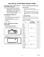
Remove 3 Screws from the back lid. (Fig. 1-1)
2. Added J1 (Jumper Wire) to the remote control
CBA. (Fig. 1-2)
How to set up the service mode:
Service mode:
1. Use the service remote control unit.
2. Turn the power on. (Use main power on the TV
unit.)
3. Press [SLEEP] button on the service remote
control unit. Version of micro computer will be
displayed on the LCD or display. (Ex: 0008GP-
0.08)
1. Initial Setting
General:
Enter the Service mode. (See page 5-1.)
Set the each initial data as shown on table 1 below.
Table 1: Initial Data
Fig. 1-1
Screws
Remote control unit (bottom)
Fig. 1-2
J 1
Remote Control CBA
Item
Button
(on the service
remote control)
Data
Value
BRT
[MENU]
→
[1]
128
CNT
124
CLR-R
64
CLR-B
64
TNT
128
V-TNT
128
SHR
112
S-BRT
[MENU]
→
[2]
128
S-CNT
128
S-CLR-R
64
S-CLR-B
64
S-TNT
128
S-SHR
112
C-BRT
[MENU]
→
[3]
128
C-CNT
128
C-CLR-R
64
C-CLR-B
64
C-TNT
128
C-SHR
112
Содержание EWL20S5
Страница 27: ...8 3 Main 1 5 Schematic Diagram L2601SCM1 ...
Страница 28: ...8 4 L2601SCM2 Main 2 5 Schematic Diagram ...
Страница 29: ...8 5 Main 3 5 Schematic Diagram L2601SCM3 ...
Страница 30: ...8 6 L2601SCM4 Main 4 5 Schematic Diagram ...
Страница 32: ...8 8 L2601SCF Function Schematic Diagram ...
Страница 33: ...8 9 L2601SCIR IR Sensor Schematic Diagram ...
Страница 34: ...8 10 L2601SCI Inverter Schematic Diagram ...
Страница 38: ...8 14 Inverter CBA Top View BL2500F01021 Inverter CBA Bottom View ...
Страница 52: ...EWL20S5 L2601UB 2006 05 29 ...


