Emerson CROSBY STYLE HC ISOFLEX Скачать руководство пользователя страница 7

7

50 (3.45)

1 (1.4)

1 (1.4)

2 (2.7)

2 (2.7)

100 (6.89)

2 (2.7)

3 (4.1)

4 (5.4)

4 (5.4)

150 (10.34)

2 (2.7)

4 (5.4)

5 (6.8)

6 (8.1)

200 (13.79)

3 (4.1)

5 (6.8)

7 (9.5)

8 (10.8)

250 (17.24)

4 (5.4)

6 (8.1)

9 (12.2)

10 (13.6)

300 (20.68)

5 (6.8)

7 (9.5)

11 (14.9)

12 (16.3)

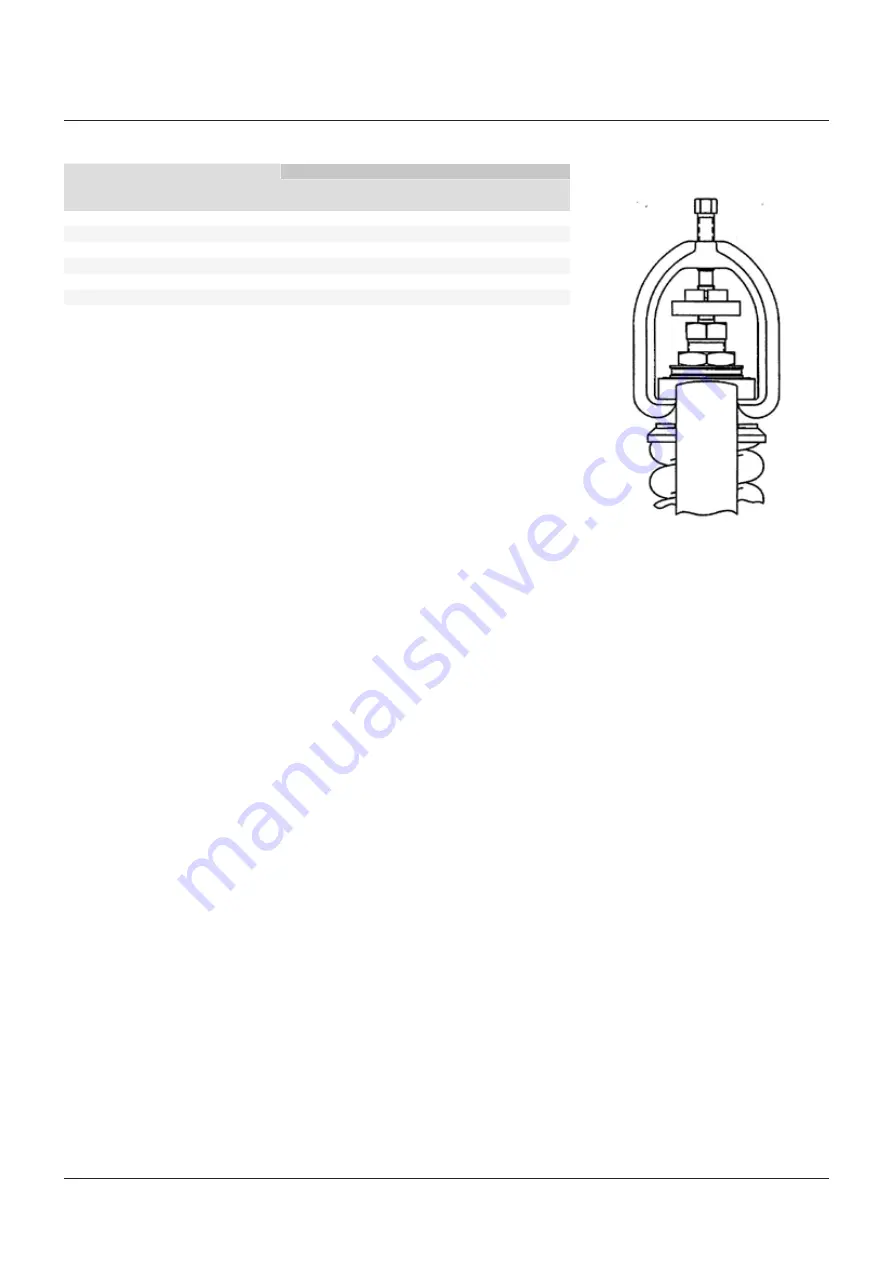
Hydrostatic test using gag

The safety valve test gag shown in Figure 5 can 
be used with both welded and flanged inlets, 
but at pressures no greater than 10% above the 
nameplate set pressure.
Gagging should be done very carefully in 
order not to overload the valve spindle or 
cause damage to the valve seats.
The following outlines the recommended 
procedure for gagging valves for 
hydrostatic test:

• Remove the lever (27), forked lever (30), 

cap (25) and spindle nut (23).

• Refer to Figure 5. Lubricate the threads and 

pointed end of the gag screw. Install the 
gag in place, being careful that the legs fit 
uniformly. Contacts on both legs of the gag 
should seat evenly on the underside of the 
bonnet top.

• Tighten the gag finger-tight only at this point.
• Raise the system pressure to approximately 

100 psig below the nameplate set pressure 
of the safety valve.

• Apply the necessary torque to the gag in 

accordance with the value shown in the 
table above for the specific orifice size. This 
torque value is determined as follows:

  -  Determine Δ by subtracting the valve set 

pressure from the hydrostatic test pressure.

  -  Read the value of Δ on the vertical scale. 

Proceed horizontally to the appropriate 
orifice size and then down to read the 
torque on the horizontal scale.

  -  The torque values (foot-pounds) obtained 

should be increased by a factor of 
approximately 25% to account for normal 
variations in friction, safety valves and 
test conditions.

CAUTION

Gags should not be used when inlet pressures are 
more than 10% greater than the safety valve set 
pressure. Damage to the valve may result.

CAUTION

Should any safety valve show seat leakage, the 
pressure must be lowered until the leakage stops.

CAUTION

Never increase the gagging load while a safety 
valve shows seat leakage. This can result 
in damage to the valve seats and bending 
of the spindle.

CAUTION

Valve gags should not be left on the valves in 
a gagged or loaded position for an extended 
period or under conditions where large thermal 
variations are expected.

FIGURE 5 - VALVE GAG
POSITION GAG EVENLY ON BONNET

• The torque should then be increased on the 

gag about 10% above the initial torque value.

• After the hydrostatic test, the pressure on the 

system should be dropped to approximately 
100 psi below the nameplate set pressure of 
the safety valve. The gags should be loosened 
at this point and removed from the valves.

• After the hydrostatic test, the gag should be 

removed and the cap reinstalled according 
to Section 10 - paragraph 'Assembly of cap'.

NORMAL GAGGING LOAD in ft·lb OF TORQUE (Nm) VS. ΔP

ΔP

Orifice

(Overpressure less valve set pressure) 
psi (bar)

psi (bar)

K

K

2

M

M

2

CROSBY

®

 STYLES HC AND HCA ISOFLEX™ SAFETY VALVES

INSTALLATION, MAINTENANCE AND ADJUSTMENT INSTRUCTIONS

• After applying the necessary torque to the 

gags, increase the hydrostatic test pressure 
to the required amount. Observations should 
be made during the rising pressure cycle to 
determine if any of the safety valves show 
seat leakage.

Содержание CROSBY STYLE HC ISOFLEX

Страница 1: ...ief product Precautionary statements in the form of warnings cautions and notes are used throughout this instruction to emphasize important and critical factors where applicable Examples WARNING An operating procedure or practice which if not observed strictly may result in injury to personnel or loss of life CAUTION An operating procedure or practice which if not observed strictly may result in d...

Страница 2: ...nnet stud nut 16 Spring 3 17 Bottom spring washer 3 18A Top spring washer 3 18B Bearing pin 3 18C Locking pin 3 19 Bearing adapter 20 Bearing 21A Adjusting bolt 21B Adjusting bolt bearing 22 Adjusting bolt nut 23 Spindle nut 24 Spindle nut cotter 1 25 Cap 26 Cap set screw 27 Lever 28 Lever pin 29 Lever pin cotter 1 30 Forked lever 31 Forked lever pin 32 Forked lever pin cotter 1 34 Test clamp 36 T...

Страница 3: ...installation and maintenance procedures specified in this manual will provide the utmost in safety a minimum of maintenance and a long service life Style HC is a high capacity reaction type safety valve designed for saturated and superheated steam applications to temperatures of 750 F Crosby Style HCA is a high temperature version of the Style HC with an alloy steel construction suitable to temper...

Страница 4: ... 1 page 5 CROSBY STYLES HC AND HCA ISOFLEX SAFETY VALVES INSTALLATION MAINTENANCE AND ADJUSTMENT INSTRUCTIONS Ordering spare parts When ordering spare parts the valve size style and shop number and or serial number should be given together with set pressure part name and reference number The valve assembly number is shown on the valve nameplate as Shop number Spare parts may be ordered from any Em...

Страница 5: ...s are directed or piped to a safe disposal area Welding of welded inlet valve body to boiler Welded inlet safety valve bodies should be welded to the boiler in accordance with applicable Code requirements The protective cover Figure 3 should be left in place until ready for the hydrostatic test of the unit If visual inspection is necessary the protective cover may be removed but should be replaced...

Страница 6: ...tion 4 paragraph Factory preparation of welded inlet valves for shipment and Figure 3 Hydrostatic tests of these valves shall be conducted using hydrostatic test plugs as detailed in paragraph below Hydrostatic testing using hydrostatic test plugs Flanged inlet safety valves Flanged inlet safety valves should not be installed for hydrostatic testing Blank flanges should be used instead of gagging ...

Страница 7: ...alues foot pounds obtained should be increased by a factor of approximately 25 to account for normal variations in friction safety valves and test conditions CAUTION Gags should not be used when inlet pressures are more than 10 greater than the safety valve set pressure Damage to the valve may result CAUTION Should any safety valve show seat leakage the pressure must be lowered until the leakage s...

Страница 8: ...king device see Figure 14 Refer to instruction I 1167 for detailed instructions in the use of this device After the spacer blocks have been removed set the nozzle ring 3 and guide ring 10 according to Section 10 paragraph Setting of rings Lock the nozzle ring set screw 4 and the guide ring set screw 11 in place making sure that the proper set screws are installed and engaged fully in a notch Lock ...

Страница 9: ...e table Repeat the same sequence of tightening to the torque value shown Then starting with the number 1 nut tighten each nut in order in a clockwise or counterclockwise direction to the value shown in the table above 5 Wipe off excess lubricant Complete the valve assembly with the cap assembly as described in Section 10 paragraph Assembly of cap and seal wire the cap set screws The sharp opening ...

Страница 10: ... and the hydraulic set pressure device Refer to test procedure T 1652 for detailed instructions in the use of the air set pressure device and instruction I 11288 for detailed instructions in the use of the hydraulic set pressure device System pressure The second method of set pressure testing is by raising the system pressure and popping the safety valve Set pressure testing using this method will...

Страница 11: ...reached or if it does not pop at the nameplate set pressure the following steps for set pressure adjustment should be taken WARNING Set pressure adjustment should not be made until the system pressure is 10 to 20 below the actual popping pressure of the safety valve The adjusting bolt should never be turned when the vessel pressure is near the set pressure of the safety valve Remove the lever 27 f...

Страница 12: ...s are custom fitted to each safety valve and should never be interchanged The spring washers are fitted to each end of the spring The spring and washers must be kept intact as a unit Before disassembly spare parts and service equipment such as lapping compound lapping blocks and jacking gear should be available Disassembly Disassembly retaining spring compression If the safety valve is to be recon...

Страница 13: ...he guide Remove the spindle 12 from the disc insert 5 by lifting the spindle slightly to engage the threads and unscrewing the spindle from the disc insert Unscrew the nozzle ring 3 from the nozzle 1B CROSBY STYLES HC AND HCA ISOFLEX SAFETY VALVES INSTALLATION MAINTENANCE AND ADJUSTMENT INSTRUCTIONS Disassembly without retaining spring compression To disassemble the safety valve completely and not...

Страница 14: ... with this compound lap again with fine compound using a new lapping block surface The first step can be omitted unless much lapping is called for Next lap again using a polish compound CAUTION Never lap the disc insert against the nozzle CROSBY STYLES HC AND HCA ISOFLEX SAFETY VALVES INSTALLATION MAINTENANCE AND ADJUSTMENT INSTRUCTIONS Repair procedure Lapping or refurbishing of valve seats Good ...

Страница 15: ...nsert seats When the damage to the disc insert 5 seat is too severe to be removed by lapping the disc insert should be replaced Disc inserts should never be remachined Remachining the insert will change critical dimensions affecting the operation of the safety valve The disc insert seating surface may be lapped if the minimum seat height shown in Figure 10 is maintained Refurbishment of nozzle sea...

Страница 16: ... Never Seez is manufactured by Bostik Corporation 2 Molykote is manufactured by Dow Corning Corporation Stand assembly on a clean surface making certain that the end of the spindle rotates freely on the disc insert bearing surface not loading on the insert threads Thread the disc holder retainer down until it makes contact with the disc holder Locate the hole in the spindle relative to a notch on ...

Страница 17: ...pindle threads with a light coat of Never Seez Molykote G or equivalent Thread the appropriate spindle adapter 6 on the spindle until it comes in contact with the jacking device piston Attach the hand operated hydraulic pump 7 and hose 8 To raise the valve spindle pressure is applied to the jacking device assembly with the hand operated hydraulic pump This activates the piston 2 which will rise co...

Страница 18: ...htened Assembly of cap see Figure 1 The assembly of the cap is referred to several times in this instruction The cap assembly consists of the spindle nut 23 cap 25 forked lever assembly forked lever 30 forked lever pin 31 and forked lever pin cotter 32 and the lever assembly lever 27 lever pin 28 and lever pin cotter 29 11 SPARE PARTS Emerson recommends spare parts as shown on the parts list with ...

Страница 19: ...VICE REQUIREMENTS Field service Crosby operates an extensive field service organization capable of adjusting setting and maintaining Crosby valves worldwide Emerson service technicians factory trained and long experienced in servicing safety valves are located throughout the world for fast response to our customers needs It is strongly recommended that on new installations a Emerson service techni...

Отзывы: