


15
3.0°
1.5°
45°
.014
.010
.008
.014
.010
.008
4.203
4.203
5.141
4.953
5.641
5.453
6.328
(106.756)
(106.756)
(130.581)
(125.806)
(143.281)
(138.506)
(160.731)
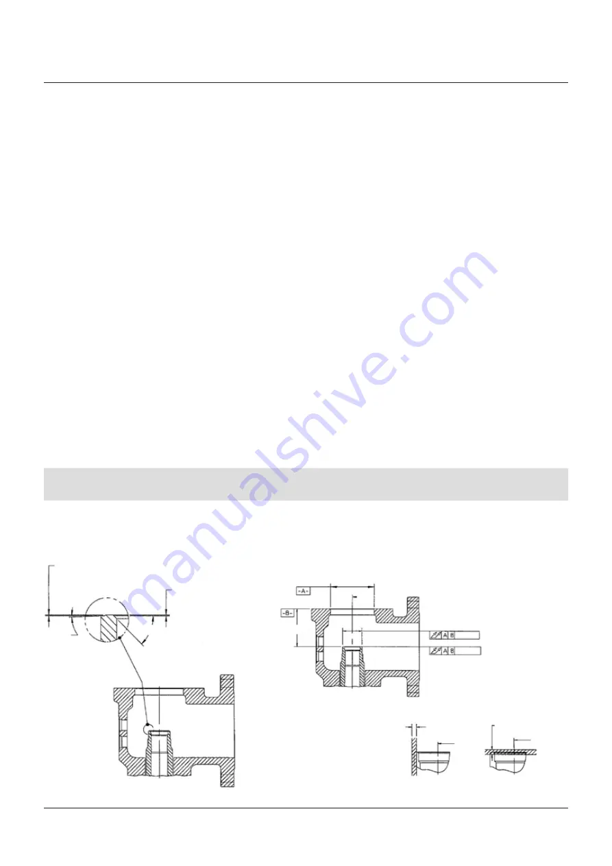
FIGURE 11 - NOZZLE SEAT CRITICAL DIMENSIONS
FIGURE 12 - BODY TO NOZZLE SEAT DIMENSIONS
Mach.
Min. after lapping
Mach.
Min. after lapping
Note 1
Note 2
Tolerance zone
parallel to datum
axis
Tolerance zone
perependicular
to datum axis
Datum
axis
Datum
axis
Datum
axis
'A' max
MAXIMUM ‘A’ DIMENSION - ORIFICE AND VALVE CLASS
K
K
2
K
2
M and M
2
M and M
2
K and K
2
M and M
2
3( ) - 9( )
3( ) - 6( )
7( ) - 9( )
3( ) - 7( )
8( ) - 9( )
11( )
11( )
in (mm)
in (mm)
in (mm)
in (mm)
in (mm)
in (mm)
in (mm)
Lap the block against the seat. Never rotate
the block continuously, but use an oscillating
movement.
When all the nicks and marks have
disappeared, remove all the compound from
the block and seat. apply polish compound to
another block and lap the seat with this. As the
lapping nears completion, only the compound
left in the pores of the block should be
present. This should give a very smooth finish.
If scratches appear, the cause is probably
dirty lapping compound. These scratches
should be removed by using compound free
of foreign material.
Be extremely careful to keep the seats flat.
Refurbishment of disc and disc insert seats
When the damage to the disc insert (5) seat is
too severe to be removed by lapping, the disc
insert should be replaced. Disc inserts should
never be remachined. Remachining the insert
will change critical dimensions, affecting the
operation of the safety valve. The disc insert
seating surface may be lapped if the minimum
seat height shown in Figure 10 is maintained.
Refurbishment of nozzle seats
If machining of the nozzle (1B) seat or other
major repairs are necessary, it is recommended
that a reseating machine be used (see Section
13 - 'Maintenance equipment'). All parts
must be accurately machined per Emerson
specifications. No safety valve will be tight nor
will it operate properly unless all parts are
machined correctly.
Machining dimensions for Crosby Style HC/HCA
safety valves are shown in Figure 11. Remove
only enough metal to restore the surface to its
original condition. Turning to the smoothest
possible finish will facilitate lapping.
The nozzle (1B) must be replaced when
the maximum 'A' dimension is exceeded.
This critical dimension is shown in Figure 12.
Interpretation
NOTES
1. Maximum tolerance zone for surface parallel
to datum axis:
for orifice K
2
through M
2
.009”
2. Maximum tolerance zone for surface
perpendicular to datum axis:
for orifice K
2
through M
2
.0015”
CROSBY
®
STYLES HC AND HCA ISOFLEX™ SAFETY VALVES
INSTALLATION, MAINTENANCE AND ADJUSTMENT INSTRUCTIONS


