C6.3.2/0416-0716/E
19
NOTE: For more information please refer to Technical Information D7.8.4 "CoreSense
™
Diagnostics for Stream refrigeration compressors".
4.6 CoreSense
™ Protection
4.6.1 Motor protection
Stream Digital compressors with "-P" at the end of the description are equipped with a
CoreSense Protection device. The temperature-dependent resistance of the thermistor (also
PTC-resistance) is used to sense the winding temperature. Two chains of three thermistors each
connected in series are embedded in the motor windings in such a manner that the temperature
of the thermistors can follow with little inertia.
The CoreSense Protection module switches a control relay depending on the thermistor
resistance. It is installed in the terminal box to which the thermistors are connected.
NOTE: The maximum test voltage for thermistors is 3V.
The total resistance of the thermistor chains on a cold compressor should be ≤ 1800Ω.
Protection class of the module: IP20.
IMPORTANT
Different sources for power supply and contact 11-14! Module
malfunction!
Use the same potential for the power supply (L) and the switch
contact of the control loop (11-14).
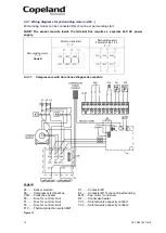
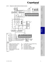
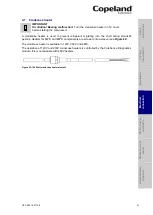
Control circuit wiring:
Figure 19: Control circuit wiring diagram
4.6.2 Oil pressure control
The oil pressure switch breaks the control circuit when the pressure difference between the oil
pump outlet and the crankcase is too low. The switch must be properly adjusted and tamper-
proof. If the oil differential pressure drops below the minimum acceptable value the compressor
will stop after a 120-second delay. After having solved the problem the control has to be reset
manually.
NOTE: Proper oil pressure safety control with an approved switch is a condition of
warranty!
The following oil pressure switches can be delivered as accessories:
Electronic oil pressure switch OPS2
Mechanical oil pressure switch Alco Control FD-113ZU
4.6.2.1
Electronic oil pressure switch
– OPS2
The specifications for the OPS2 oil pressure switch are as follows:
Differential pressure: 0.95 ± 0.15 bar
Time delay:
120 ± 15 sec.
S
afet
y
in
struct
ion
s
P
ro
d
u
ct
d
es
cr
ipt
ion
Inst
all
atio
n
E
lec
tr
ica
l
c
o
n
n
ec
tion
S
tar
ting
up
&
o
p
er
atio
n
Ma
int
enan
c
e &
repai
r
Dismant
ling
&
d
ispo
sa
l

