background image

CLARKSON

 KNIFE GATE VALVE MODEL ZP3OO

INSTALLATION AND MAINTENANCE INSTRUCTIONS

Before installation these instructions must be fully read and understood

GENERAL INFORMATION

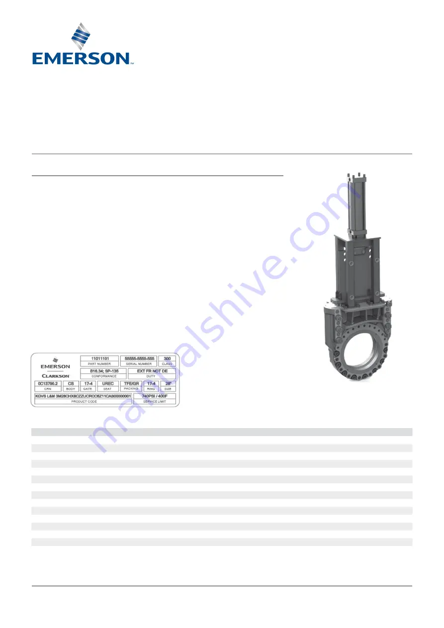
LABEL CONTENTS

Item

Description

Example

Product code

Manufacturer’s model/code

KGVS Clarkson 3M28CHX8CZZUCRCC6Z11CAB00000001

Part number

Manufacturer’s pn

11011101

Serial number

Manufacturer’s sn

55555-5555-555

Size

NPS valve size

28

Class

Pressure rating per conforming standard

300

Duty

Type of service depending on valve configuration (ext or int mounted flow ring will change duty) EXT FR NOT DE or INT FR DE

Ring material

Compliance standard for flow ring material

17-4

Service limit

Limits in pressure and temperature operation

740psi/100F

Conformance

Standard used for design and manufacture

ASME B16.34, MSS SP-135

Crn

Canadian registration number

0C13790.2

Body material

Compliance standard for body material

WCB/LCB

Gate material

Compliance standard for gate material

17-4

Seat material

Seat material

URET

Packing material Packing material

TPE/GR

COMPLIANCE LABEL

3.  Mating line flanges must be properly 

aligned. Slip-on or weld flanges can be used. 
Never try to make up for misaligned pipe 
flanges by the line bolting.

4.  Flange fasteners should be tightened in a 

uniform manner using a cross-pattern to 
prevent distortion of the valve. 

5.  Pipe supports and/or expansion joints should 

be used to minimize pipe loads on valves. 
ZP300 valves are suitable for use in either 
vertical or horizontal lines. If installation is 
other than vertical, additional support will be 
required for cylinder actuated valves.

© 2017 Emerson. All Rights Reserved.

Emerson.com/FinalControl

VCTDS-03757-EN 16/12

The Clarkson ZP300 knife gate valve is 
designed to meet extremely rugged and 
challenging requirements of expansible fluid 
applications in the oil sands processes.

Please take note of specific installation tags 
provided with each ZP300 series valve.

1.  Compliance to ASME B16.34 Class 300, 

Valves-Flanged, Threaded, and Welding End 
and MSS SP 135 (Long Face-to-Face).

2.  Bi-directional valve, no special concerns 

in relation to direction of flow are required 
when installing the valve.

Содержание Clarkson ZP300

Страница 1: ...ial Seat material URET Packing material Packing material TPE GR COMPLIANCE LABEL 3 Mating line flanges must be properly aligned Slip on or weld flanges can be used Never try to make up for misaligned pipe flanges by the line bolting 4 Flange fasteners should be tightened in a uniform manner using a cross pattern to prevent distortion of the valve 5 Pipe supports and or expansion joints should be u...

Страница 2: ...s are design to suit flanges compliant to ASME B16 5 and B16 47 and gaskets designed to ASME VIII 1 Appendix 2 and ASME B16 20 and B16 21 Torque on Flange bolt should not exceed values shown in Table 1 TABLE 1 MAXIMUM TORQUE ON FLANGE BOLT STUD Valve size NPS Bolt size Torque ft lb Recommended bolt length in Recommended stud length in INITIAL INSPECTION NOTES 1 Maximum torque should not be exceede...

Страница 3: ...cylinder design and mounting arrangement HYDRAULIC CYLINDER SIZE AND REQUIRED FLOW RATE Valve size NPS HC size Rod size Fluid flow rate in 3 sec 1 in s Max close 1 in s Max open WARNING To minimize stress concentration in flow ring ensure flange gasket ID is matched with flow ring ID as shown in Figure 2 GASKET DETAIL FIGURE 2 Gasket Gasket ID matched to flow ring ID Flow ring with overlay HYDRAUL...

Страница 4: ...tor 6 Electric motor actuated valves should be left in their factory set condition unless the system operating parameters dictate a change If changes are necessary they should be performed in small increments using the lightest lowest setting possible to achieve the desired performance and then the valve actuator function inspected Excess torque and or thrust in the motor settings may damage or lo...

Страница 5: ...essive corrosion bitumen build up tears in rod boot etc Check rod boot connections Check for cylinder rod seal blow by FIGURE 11 Major components Cast body Polymer liner UHMPW PE Polyurethane seat Body O ring 17 4PH gate Packing gland Packing Gate scraper Flow ring Flow ring O ring 2 Packing gland check for leaks or worn packing If leakage is occurring around the packing gland tighten the packing ...

Страница 6: ... compressed to obtain an elongated smaller piece Note not all sizes have smaller end pieces some will have equal size end pieces 6 Install packing gland with studs Bellville Washers and nuts as shown in Figure 17 For initial tightening of packing gland tighten packing gland to achieve a compression between 0 125 0 375 Use Loctite 262 Red on studs to secure in body Note ensure each stack is facing ...

Страница 7: ...27 000 16 2 78 16 2 76 24 50 27 630 16 2 78 8 2 76 25 00 28 000 8 2 78 16 2 76 28 4 25 00 26 50 30 000 24 3 00 27 00 30 130 8 3 00 16 2 95 30 4 27 00 1 32 000 1 8 3 22 24 2 95 28 50 1 32 500 1 16 3 22 29 00 1 32 750 24 3 22 32 4 29 00 1 34 500 1 24 3 41 1 31 00 1 35 380 1 8 3 41 16 3 41 36 4 33 00 1 38 500 3x1 24 3 68 34 50 1 39 000 1 16 3 68 8 3 68 35 00 1 39 375 1 8 3 68 16 3 68 42 4 38 50 1 44 ...

Страница 8: ...NTING Cylinders may require additional support when mounted other than in vertical position Failure to do so could lead to premature failure of cylinder and or valve The following illustrations are suggestions specific details will have to be determined by customer so support best suits surrounding area It is important that the cylinder gate alignment be maintained during valve operation Supports ...

Страница 9: ...zontal position Preparation for storage Valves may be stored as shipped provided the storage facility and equipment orientation instructions above are followed If valve packaging is altered or removed for receiving inspection repackage valve as originally received Standard packaging materials cannot be considered sufficient for outdoor storage Cylinder storage These cylinder storage instructions a...

Отзывы: