background image


February 2018

Installation and Operation Manual

E2K-405-0218 Rev. 2

66

Section 5: Customizing Actuator Settings

Customizing Actuator Settings

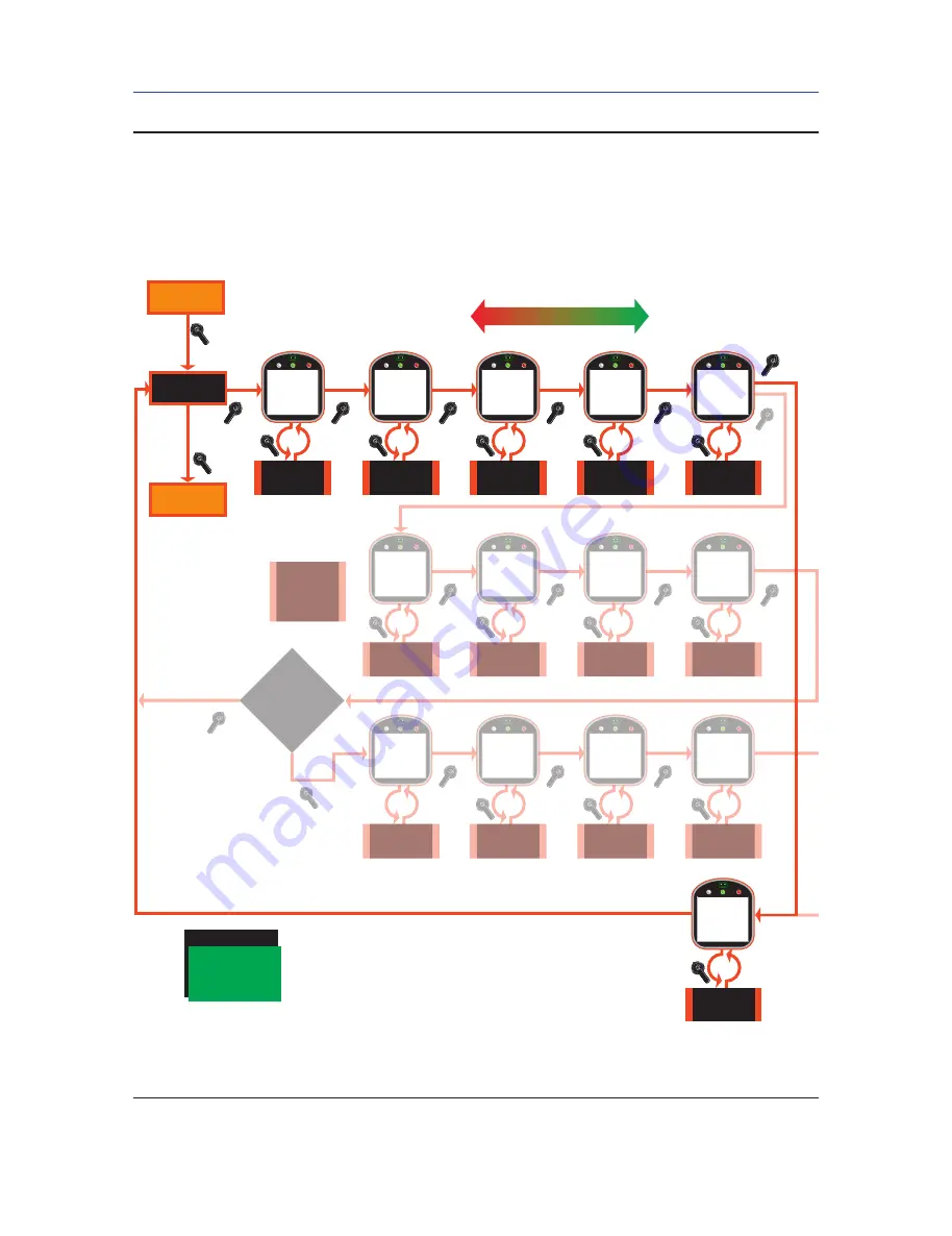
Figure 5-14 

Network Setup

NOTE: The actuator senses that the Controlinc ACM is installed and adjusts the display sequence to 
display only one output.

NO

Figure 5-14

Network Setup

NETWORK

SETUP?

Go to

Figure 5-4

Go to

Figure 5-2

YES

BACK

NEXT

Increment from

001 to 254

NO

Increment from

001 to 255

NO

Increment from

001 to 255

NO

Increment alarm

choice: 

<YES or NO>

NO

BACK

NO
OR

NEXT

YES

Network

Node Address

<xxx>

YES

Response

Delay

<xxx>MS

YES

YES

YES

YES

YES

Chan A Parity?

<parity>

Lost Comm

Delay

<xxx>MS

Enable New A

Alarm?

<alarm>

Increment parity

choice: NONE, ODD

or EVEN

NO

Write Protect?

<YES/NO>

Increment choice: 

<YES or NO> 

NO

Select Baud
Rate Choice

NO

Increment stop bit

choice: 1, 1.5 or 2

NO

Increment word

length choice: 

5, 6, 7, 8 bits

NO

YES

Chan A 

Baudrate?

<baud>

YES

YES

Enable Net B

Alarm?

Chan A

Stop Bit?

<stopbit>

Chan A

Word Length?

<wlength>

NO

NO

NO

NO

YES

YES

Chan B
Parity?

<parity>

YES

YES

Chan B

Word Length?

<wlength>

Chan B

Baudrate?

<baud>

Chan B

Stop Bit?

<stopbit>

Increment parity

choice: NONE, ODD

or EVEN

FUTURE 

RELEASE

Factory

Network

Adapter is Controlinc OR

DeviceNet OR FF BlockMode OR 

FF Mod. Mode OR

Profibus 

Increment alarm

choice: 

<YES or NO>

Select Baud
Rate Choice

Increment stop bit

choice: 1, 1.5 or 2

Increment word

length choice: 

5, 6, 7, 8 bits

4800, 9600, 1440,

19200, 38400,

57600, 115200 &

128000

BAUD RATE:

All manuals and user guides at all-guides.com

Содержание Bettis TEC2

Страница 1: ...Installation and Operation Manual E2K 405 0218 Rev 2 February 2018 TEC2 Electric Actuator with Model 500 All manuals and user guides at all guides com a l l g u i d e s c o m ...

Страница 2: ...All manuals and user guides at all guides com ...

Страница 3: ...trol Module ACM Optional 17 3 6 1 Wiring the ACM 17 3 6 2 Analog Controlled Power Supply Connections 19 3 6 3 Network Controlled 22 3 7 Auxiliary Relay Module ARM Wiring 23 3 8 Remote Display Module RDM Connection to the Actuator Optional 25 3 8 1 24 Vdc Power Source 26 3 8 2 115 230 Vac Power Source 27 3 8 3 Two RDMs One 24 Vdc and One 115 208 220 230 Vac Power Source 27 3 8 4 RDM Connections and...

Страница 4: ...5 9 Network Setup CAM and Controlinc ACM Required 65 5 5 10 Tag Name Setup 68 5 5 11 Passcode Setup 69 5 5 12 Reload Factory Settings 71 Section 6 Troubleshooting 6 1 Troubleshooting Problems Corrective Action for Actuator Operation 72 6 2 Display Diagnostics 73 6 2 1 Display Alarm Log 74 6 2 2 Display Torque Profile 75 6 2 3 Display Torque Archive 76 6 2 4 Display Operation Log 76 6 2 5 Display O...

Страница 5: ... A A 1 Exploded View Model 500 Torque Unit Only 82 A 2 M 500 with Thrust Base Installation Drawing 83 A 3 Module Identification and Location 85 A 4 Infrared Controller IRC Clicker 86 A 5 IrDa Port 87 A 6 Disconnect Circuit Breaker 87 A 7 Common Bolt Tightening Torques 89 A 8 Bluetooth Specifications 91 All manuals and user guides at all guides com ...

Страница 6: ...CM Network Control Module 18 Figure 3 11 ACM Wiring Connections 18 Figure 3 12 ACM Analog Output with External Power Supply 19 Figure 3 13 ACM Analog Output with Internal Power Supply 19 Figure 3 14 ACM Analog Input with External Power Supply 20 Figure 3 15 ACM Analog Input with Internal Power Supply 20 Figure 3 16 Futronic 3 Wire Analog Control with External Power Supply 21 Figure 3 17 Futronic 3...

Страница 7: ...Timer Setup 58 Figure 5 13 Analog Setup 60 Figure 5 13 1 Analog Input 1 Calibration Setup 61 Figure 5 13 2 Analog Input 2 Calibration Setup 62 Figure 5 13 3 Analog Output 1 Calibration Setup 63 Figure 5 13 4 Analog Output 2 Calibration Setup 64 Figure 5 14 Network Setup 66 Figure 5 14 1 Network Setup Display Menu 67 Figure 5 15 Tag Name Setup Menu 68 Figure 5 16 Passcode Setup Menu 69 Figure 5 17 ...

Страница 8: ...27 Table 3 4 RDM Connections with External Power Source External AC 27 Table 3 5 Dip Switch SW5 and SW6 Settings 27 Table 4 1 LDM Rotating Knobs 30 Table 4 2 Normal Display Functions 31 Table 4 3 RDM and LDM Operation Priority 32 Table 4 4 Default Configuration Settings 34 Table 5 1 Relay Outputs 1 through 5 Configuration 53 Table 5 2 Relay Output Function List 54 Table 5 3 Relay Outputs 9 through...

Страница 9: ...l injury or equipment damage NOTE Highlights information critical to the user s understanding of the TEC2 valve actuator installation or operation 1 2 Purpose This installation and operation manual explains how to install operate and maintain the TEC2 valve actuator TEC2 actuators are intended for automating part turn and multi turn valves within the specified torque ranges for given model WARNING...

Страница 10: ...ipped from the factory providing that all compartment covers and cable entry plugs remain intact The actuator should be immediately stored in a clean dry warehouse free from vibration and rapid temperature changes until it can be installed and energized If the actuator must be stored outside it should be stored off of the ground at an elevation sufficient to prevent it from being immersed in water...

Страница 11: ...uator The alarm message SET LIMITS BEFORE OPERATING will be displayed The alarm icon and the yellow LED will be flashing Valve position will be displayed as EE 2 The instruction is based on valve being in closed position If valve is at Open end of travel you must move the valve in Close direction and set a dummy close limit Then move back to Open and set the open limit Save the limits Proceed as f...

Страница 12: ...the selector knob in the STOP position ACCEPT CLOSE LIMIT will be displayed 3 Rotate the control knob to YES SELECT LOCAL AND OPEN VALVE will be displayed The close limit is set C Set open valve travel limit 1 Valve Operation 1 For Electrical Operation use the control knob to move the valve in the open direction Proceed to Step No 2 2 For Manual Operation depress the declutch lever while rotating ...

Страница 13: ...he first time At the completion of setting the limits the actuator should be in the STOP mode and the valve should be at its open limit The LDM should display 100 and the red LED should be ON The graphics display of the valve should represent full open Figure 2 1 Declutch Lever and Handwheel TEC2000 TEC2 Enclosure TEC2000 TEC2 Enclosure Model 500 Enclosure Hand Crank Handwheel Declutch Lever Declu...

Страница 14: ...etting Limits Electrical Operation Set Local and Close Valve Close Valve Then Select STOP Use Control Knob to Move Valve to Close direction When done select STOP Accept Valve Close Limit Set Local And Open Valve Accept Valve OPEN Limit Save Limits Rotate Selector Knob NEXT to Toggle Through The Displays EXIT Open Valve Then Select STOP Use Control Knob to Move Valve to Open direction When done sel...

Страница 15: ...e Valve Close Valve Then Select STOP Accept Valve Close Limit Set Local And Open Valve Open Valve Then Select STOP Accept Valve OPEN Limit Save Limits Rotate Selector Knob NEXT to Toggle Through The Displays EXIT Declutch actuator Rotate handwheel to Close position limit When done select STOP Declutch actuator Rotate handwheel to OPEN position limit When done select STOP Figure 2 3 Setting Limits ...

Страница 16: ...e control knob to NO to increment the address numbers Hold in the NO position until the desired address is reached NOTE If the desired address is a lower number than what is displayed continue to increment the numbers until the highest numbered address is reached The address numbers will then start with the lowest numbered address and continue to increment 5 When the correct address is displayed r...

Страница 17: ...t or void warranty WARNING Use caution when working on with or around valves and actuators High pressures forces voltages and flammable media can be present 3 1 Preparing the Stem Nut NOTE The actuator can be direct mounted to the valve shaft or stem or can be close coupled to the auxiliary gear drives See Appendix for the appropriate drawings Figure 3 1 Preparing the Stem Nut TEC2000 TEC2 Enclosu...

Страница 18: ... diameter deep into the actuator base 4 Screw the Stem Nut piece 54 onto the Stem until it enters the Drive Sleeve 5 Place Key piece 52 in line with the Drive Sleeve Keyway Insert Key piece 52 6 Turn the handwheel in the Open direction to pull the Stem Nut piece 54 into the Drive Sleeve until it bottoms out NOTE Valve will begin to open 7 Place the Locknut piece 55 over the Valve Stem Screw the Lo...

Страница 19: ...moving STC Cover Multiple power sources may exist under the cover NOTE Valve actuator requires a circuit breaker within the line of sight sized for the motor currently specified on the nameplate See Appendix Section A 7 for the circuit breaker options Remove cover with a strap wrench drift or pinch bar by rotating the cover counterclockwise Figure 3 2 Removal of STC Cover TEC2000 TEC2 Enclosure Mo...

Страница 20: ...ing captive plates Connections can be made one of three ways Strip and connect bare wire Strip and install wire ferrule Strip and install crimp on insulated or non insulated ring or fork tongue connectors for either M3 control signal terminal block screws or M4 power terminal screws 1 Loosen terminal block connectors L1 L2 L3 and GND screws with a common or Phillips head screwdriver 2 If bare wire...

Страница 21: ...ns are screw size M4 The control connection screw size is M3 3 3 5 Replace Terminal Compartment Cover To replace the cover follow the steps detailed in Section 3 3 1 Remove Separate Terminal Chamber STC Cover in reverse order NOTE Clean electrical enclosure threads thoroughly and lightly grease with a dielectric grease before closing 3 3 6 External Earth Ground Connections External connection poin...

Страница 22: ...on the standard unit and the Auxiliary Relay Module ARM will continue to operate This option permits testing or setting up the actuator without applying main power The DBM can be provided as an option with the TEC2 or it can be purchased later If purchased separate install as follows If provided with the TEC2 proceed with Step No 2 to activate 1 Mount the DBM under the Auxiliary Control Module ACM...

Страница 23: ...eries can be installed for extended life 3 5 Discrete Controlled Inputs The actuator can be controlled by discrete inputs two wire control three wire control four wire valve control Connect the power for these discrete inputs as detailed in Figure 3 6 Control Input Wiring for external and internal power source Figure 3 7 details connections for Inhibit and ESD wiring See Section 3 3 Electrical Con...

Страница 24: ...ose Inhibit ESD 0V common External Power Supply 18 150 VDC or 20 250 VAC 0V common 5 6 7 8 24 VDC 10 9 Internal Power Supply NOTE See Section 3 6 2 Analog Controlled Power Supply Connections for 3 wire analog Figure 3 8 TEC2 Partial Stroke Test PST Wiring Diagram 3 4 14 15 16 10 9 PST Start Green Light PASS Red Light FAIL Stop PST Common 24 VDC 0 VDC RO 4 Common RO 3 TEC2 STC Connections PST Box A...

Страница 25: ...inside the round cover nearest the display end The Futronic or Controlinc ACM connects to the Central Control Module CCM for logic control functions and to the Separate Terminal Chamber STC for user wiring connections To wire the ACM connect the wires in accordance with Figure 3 9 and Figure 3 10 as applicable See Section 3 3 Electrical Connections for general electrical connection requirements Fi...

Страница 26: ... Port Emergency Stop N C Remote Display Model Communication Port Earth Ground 1 3 5 7 9 11 13 15 17 19 21 23 2 4 6 8 10 12 14 16 18 20 22 24 26 28 30 32 34 36 38 40 42 44 25 27 29 31 33 35 37 39 41 43 Open Close Stop Open Inhibit Close Inhibit ESD Digital Input 1 Digital Input 2 Digital Input 3 Digital Input 4 Digital Input 5 Digital Input 6 Common 0V for Control Inputs 1 3 Common 0V for Inhibit E...

Страница 27: ... Supply Connections The power sources for analog controlled inputs outputs are either internal or external Connect the power supplies as shown in Figure 3 12 through Figure 3 17 Figure 3 12 ACM Analog Output with External Power Supply Figure 3 13 ACM Analog Output with Internal Power Supply All manuals and user guides at all guides com ...

Страница 28: ...tion 3 Installation Installation Figure 3 14 ACM Analog Input with External Power Supply Figure 3 15 ACM Analog Input with Internal Power Supply 25 26 27 28 29 AIN 1 AIN 2 Earth 24 VDC 10 9 25 26 27 28 AIN 1 AIN 2 Earth 24 VDC 29 All manuals and user guides at all guides com ...

Страница 29: ... Set Point Earth Ground 24VDC 9 10 25 26 29 Open Open 18 150VDC or 20 250VAC External Power Supply Close 3 Wire Common 0v Close Toggle 1 2 3 4 External Power Supply AIN 1 4 20mA Position Set Point Earth Ground External 24VDC Input Z 25 26 29 Figure 3 16 Futronic 3 Wire Analog Control with External Power Supply Figure 3 17 Futronic 3 Wire Analog Control with Internal Power Supply All manuals and us...

Страница 30: ...chnicians using a special passcode to enter the FACTORY SETUP mode Connect the actuators as shown in Table 3 1 for RS 485 redundant bus or E Net networks If another protocol is selected then refer to the wiring diagram supplied with the actuator for connections NOTE If E Net network topology is specified insert a jumper between Terminals 40 and 42 to connect the network cable shield throughout the...

Страница 31: ...Ground 1 3 5 7 9 11 13 15 17 19 21 23 2 4 6 8 10 12 14 16 18 20 22 24 26 28 30 32 34 36 38 40 42 44 25 27 29 31 33 35 37 39 41 43 Open Close Stop Open Inhibit Close Inhibit ESD Digital Input 1 Digital Input 2 Digital Input 3 Digital Input 4 Digital Input 5 Digital Input 6 Common 0V for Control Inputs 1 3 Common 0V for Inhibit ESD Inputs 4 6 User Power Supply 24VDC Power Supply Relay Output 1 Limit...

Страница 32: ...y 2018 Installation and Operation Manual E2K 405 0218 Rev 2 24 Section 3 Installation Installation Figure 3 19 ARM Wiring Connections ARM Wiring Terminals 39 to 44 All manuals and user guides at all guides com ...

Страница 33: ...ch RDM can be powered from the actuator or it can be powered from an external source If more than one RDM is used one can receive power from the actuator and the other can receive power from an external source See Section 3 3 Electrical Connections for general electrical connection requirements NOTE If RDM 1 or 2 is enabled and not connected the actuator will be in stop mode and cannot be operated...

Страница 34: ...Belden 8723 or equivalent as detailed in Table 3 3 The cable distance is limited to 1 200 feet 366 meters NOTE By using two cables Belden 8719 or equivalent for power and Belden 9841 or equivalent for RS 485 communication the distance limitation is increased to 4 000 feet 1 200 meters Figure 3 21 RDM Interface Module Support Both 24V DC and AC P2 SW1 1 6 All manuals and user guides at all guides c...

Страница 35: ...ivalent as detailed in Table 3 4 Table 3 4 Connections with External Power Source External AC RDM Interface Module Connector P2 Function TEC2 STC Terminals P2 1 AC 115 230 Vac 50 60 Hz P2 2 AC 0V Common P2 3 CHA RS 485 21 P2 5 CHA N RS 485 23 P2 4 CHA Shield 24 3 8 3 Two RDMs One 24 Vdc and One 115 208 220 230 Vac Power Source To use two RDMs one can receive 24V DC power from the actuator and the ...

Страница 36: ... 4 5 6 7 8 11 12 13 14 15 16 17 18 19 1 1 1 5 6 7 8 10 2 3 4 9 9 10 2 4 9 10 4 10 9 1 1 1 2 3 4 5 6 7 8 2 4 4 20 21 22 23 24 36 38 9 10 GND Supply Open Close Stop Common 0V Common 0V ESD 24 VDC LSO R0 1 R0 2 R0 3 R0 4 R0 5 LSC LSB LSA Common Common Common Monitor Relay N O Contact N C Contact RS485 RS485 Separate Terminal Chamber Shield DCMlinkTM Emergency Stop Emergency Stop 0 VDC Open Inhibit Cl...

Страница 37: ...le Display Module with Bluetooth Model 87340 See Appendix for Specifications The Local Display module consists of the following as shown in Figure 4 2 Graphics Display Message Center Control Knob and Selector Knob Three LEDs Figure 4 2 Local Display Module LDM LEDs Graphics Display Message Center Control Knob Selector Knob All manuals and user guides at all guides com ...

Страница 38: ...Back display function in the MONITOR SETUP mode as detailed in Table 4 1 The NEXT and BACK selections are used strictly for cycling through the SETUP displays to locate the desired display or to exit the SETUP mode Table 4 1 LDM Rotating Knobs Knob Rotation Direction Function Result Control Spring return to center Neutral Position Completes YES or NO entry cycle Exception when knob is held for con...

Страница 39: ...layed Figure 4 3 Normal Display The valve has stopped and is 75 opened The yellow LED is ON and the message center is clear Table 4 2 Normal Display Functions Valve Activity Message Center Top Line Display Functions LEDs Position Bar Graph Percent Open XX Yellow Red Green Fully closed FULL CLOSE OFF OFF ON 0 Opening OPENING OFF Blinking OFF Flashing in the Open direction Increments Stopped Cleared...

Страница 40: ... for 5 seconds or more If RDM 1 or 2 is enabled and not connected the actuator will be in stop mode and cannot be operated until RDM is connected or disabled 4 2 1 RDM Operation with LDM Two RDMs and an LDM can be connected to one actuator The operation priority is detailed in Table 4 3 Table 4 3 RDM and LDM Operation Priority Mode of Operation LDM RDM 1 RDM 2 and Selector Switch Position STOP At ...

Страница 41: ...ed in Section 2 Quick Start Limit settings can be changed as described in Section 5 5 3 Set Valve Travel Limits Once the limits have been set check the settings as follows For Electrical Operation 1 Run actuator electrically to verify correct operation For Manual Operation 1 Move the valve in the close direction The Red LED should go off and the Green LED should blink within one handwheel turn 2 M...

Страница 42: ...n CLOSED contact RO 2 N O RO 10 N O Lost Com ESD OFF Local Control Maintain DI 6 Active on OPEN contact RO 2 Continuous RO 10 Flash Stayput on ESD ON Remote Control Maintain RO 3 LSO RO 11 Lost Phase Alarm ESD Override on Thermal OFF Torque Retry OFF RO 3 N O RO 11 N O ESD Override on Local OFF Remote Display 1 OFF RO 3 Continuous RO 11 Flash ESD Override on Stop OFF Remote Display 2 OFF RO 4 LSC ...

Страница 43: ...ed Bandwidth 5 0 Response Delay Time 8ms Delay Time 1 Second Parity NONE Input Polarity CLOSE 4mA Analog I 0 Scale 0 4095 Output Polarity CLOSE 4mA Write Protect NO STAYPUT on lost signal 1 Enter SETUP mode as detailed in Step No 2 of Section 2 Quick Start 2 Place the selector knob in the NEXT position to advance through each display until DISPLAY SETTINGS is displayed 3 Rotate the control knob to...

Страница 44: ...wire IrDA port Three wire Analog Analog ignored if ACM not installed Network ignored if ACM not installed Drive Sleeve Close cw or ccw pos or trq Position Seat Torque Backseat on off Open Torque xx Local Control LocalCtrlSetting Remote Control RemoteCtrlSetting Remote Display 2 on off Close LED color Open LED color Low Battery Alarm on off Torque Retry on off Remote Display 1 on off Close Torque x...

Страница 45: ...4 Release the knob to stop the actuator movement The knob will return to the neutral position Local Momentary Mode Seal ins Active 3 Place the control knob in either the OPEN or CLOSE position Momentarily hold for 0 5 seconds and release The actuator will move in the open or close direction to the end of travel 4 To stop the actuator movement Place the selector knob in the STOP position OR Place t...

Страница 46: ...g Setup Mode 2 Use the selector knob NEXT BACK to select CONTROL MODE under VALVE CONTROL SETUP 3 Use the control knob NO to select the desired control mode See Section 5 5 2 Valve Control Setup 4 Exit SETUP mode and place selector knob in the REMOTE position Remote Maintained Inching Mode 5 Apply the control signal and maintain After 0 5 seconds the actuator will move in the open or close directi...

Страница 47: ...contacts to open or close the valve This is an inching type mode Remote seal ins Momentary mode may be activated in the SETUP mode If the three wire control is used with the seal ins activated the valve cannot be stopped while being remotely controlled the valve can only be stopped via the inhibit or emergency stop inputs Four Wire Control The four wire control mode uses three maintained contacts ...

Страница 48: ...TE Do not hold the knob in any one position longer than 0 5 seconds 3 Rotate the control knob to YES A series of questions will be displayed as detailed in Figure 5 1 NOTE If the control knob is placed in the NO position or if NEXT or BACK is selected in lieu of YES the display will return to the normal display mode 4 Use the control knob to answer YES or NO to the displayed questions Use the sele...

Страница 49: ...5 7 YES YES Display Unit Parameters Change Settings Display Settings Display Diagnostics NO from EXIT when right knob is in STOP position YES only NEXT will not exit setup EXIT NO NO NO Go to Figure 5 3 YES Go to Figure 5 4 YES YES Go to Figure 4 5 YES YES Go to Figure 6 1 Exit Setup and revert to normal display NO NO NO NO BACK NEXT AreLimitsSet All manuals and user guides at all guides com ...

Страница 50: ... Travel Limits 5 3 Changing Display The language or the contrast can be changed as follows A passcode is not required See Figure 5 2 1 At the CHANGE DISPLAY prompt answer YES CHANGE LANGUAGE will appear 2 If English is the desired language answer NO ADJUST CONTRAST will appear Go to Step No 4 3 If English is not desired answer YES to CHANGE LANGUAGE and DISPLAY OTHER will appear The user may chang...

Страница 51: ...tag name method of control and network address may be entered or changed via the Change Settings mode See Section 5 5 Change Settings All other parameters viewed are factory setup and cannot be changed by the user NO Figure 5 2 Change Display Go to Figure 5 15 Go to Figure 5 16 YES YES Change Language Language xxxxxxxx English Spanish Portuguese Russian French Mandarin Italian German YES YES Adjus...

Страница 52: ...ss addr YES Model model turn speed S N serial MFG Date mdate YES YES YES Voltage volt ph freq MTR mtr model hp HP rpm RPM NO NO NO NO YES Run run amp Stall stl amp Torque Spring torq spring YES YES YES Max Torque max torq Batery Enable Yes No current date current time NO NO NO NO YES LDM Bluetooth enable disable RDM1 Bluetooth enable disable YES YES RDM2 Bluetooth enable disable BT Discovery enabl...

Страница 53: ...l to CHANGE SETTINGS Answer YES See Section 5 1 Entering Setup Mode 2 Enter passcode NOTE A passcode must be entered to change settings 3 Use the selector knob NEXT BACK to scan the display for the desired setting to change the following Valve control setup Valve travel limits Discrete input Discrete output Inhibit and ESD Two speed timer Analog Network Tag name Passcode All manuals and user guide...

Страница 54: ...5 9 YES Go to Figure 5 10 YES Go to Figure 5 11 YES Go to Figure 5 12 NO NO NO Two Speed Timer Setup NO BACK NEXT YES Change Display YES Go to Figure 5 2 NO YES Network Setup Change Display Tag Name Setup Passcode Setup Battery Enable NO NO Displayed only if ACM Installed and ANALOG control is enabled See Figure 5 13 Displayed only if ACM Installed and ANALOG control is enabled See Figure 5 14 YES...

Страница 55: ...will appear X will be flashing X is the first left most character in the passcode 2 If this character is correct select YES If not select NO Use NO to increment from 0 9 and then A Z until the correct character is displayed Select YES The second character will flash NOTE When Z is displayed the data will rollover to 0 and continue incrementing 3 Repeat Step No 2 for the second and third characters...

Страница 56: ... the desired choice See Figure 5 6 See Section 4 5 Remote Auto Control Operation for a description of each control mode NO Figure 5 5 Passcode Entry Go to Figure 5 3 Go to Next Display See Figure 5 4 Go to Next Display See Figure 5 4 YES YES YES Accept Passcode Character 1 0 Increment Character 0 9 A Z Passcode Reset To 000 YES Increment Character 0 9 A Z NO NO NO NO NO NO BACK NEXT BACK CHANGE SE...

Страница 57: ...que xx Local Control LocalCtrlSetting Remote Control RemoteCtrlSetting Increment torque backseat choice On or OFF Increment close torque percent 15 to 100 in 1 steps limited by factory MAX torque setting Increment local control setting momentary or maintained Increment remote control setting momentary or maintained Increment seat choice Position or Torque Increment open torque percent 15 to 100 in...

Страница 58: ...swer YES See Figures 5 7 and 5 8 Figure 5 7 Set Valve Travel Limits Normal Operation Mode Set Limits with Electrical Operation Figure 5 7 Normal Operation Mode Set Limits With Electrical Operation Go to Figure 5 6 Go to Figure 5 4 YES YES YES YES Accept Valve Close Limit Accept Valve Open Limit Use control knob to move valve in CLOSE direction When done select STOP Use control knob to move valve i...

Страница 59: ... 6 Go to Figure 5 4 YES YES YES YES Accept Valve Close Limit Accept Valve Open Limit Declutch actuator Rotate handwheel to CLOSE direction When done select STOP Save the Valve Travel Limits NO NO NO BACK NEXT NO Select Local and Close Valve Select Local and Open Valve LOCAL LOCAL Close Valve Then Select Stop Open Valve Then Select Stop BACK SETVALVE TRAVELLIMITS SAVE LIMITS STOP STOP Declutch actu...

Страница 60: ...ts For connecting a discrete input see Section 3 5 Discrete Controlled Inputs See Figure 5 9 Figure 5 9 Discrete Input Setup Configuration of discrete inputs are shown below Increase DI 1 Active Contact Choice OPEN or CLOSE Figure 5 9 Discreet Input Setup YES Go to Figure 5 4 DI 1 Active on open close CONTACT NO Increase DI 2 Active Contact Choice OPEN or CLOSE YES DI 2 Active on open close CONTAC...

Страница 61: ...nswer YES 2 Use the selector knob NEXT BACK to review the settings for Discrete Outputs 3 Use the control knob NO to select desired configuration for each relay See Figure 5 10 Table 5 1 Relay Outputs 1 through 5 Configuration Relay Default Function Configu rable Function Configure N O N C Default Setting Configure Flashing RO 1 LSO Valve full OPEN See Table 5 2 Relay Output Function List Yes N O ...

Страница 62: ...ond intervals while the function is active Table 5 2 Relay Output Function List LSO Open limit LOW BATTERY VALVE STALL LOCAL ESD LSC Close limit LOCAL VALVE DRIFT MOVED BY HANDWHEEL ESD ACTIVE LSA Intermediate limit A STOP SS OFF LOST POWER LOST ANALOG LSB Intermediate limit B REMOTE MOTOR OVERLOAD ACTUATOR FAIL OPENING OPEN TORQUE LOST PHASE HOST CONTROL Controlled by Network CLOSING CLOSE TORQUE...

Страница 63: ...lay 4 trigger Relay 4 N O N C Relay 4 cont flash Increment thru list of relay triggers see list below Increment Relay Normally Open Close Choice N O or N C Increment Relay Continuous or Flashing Choice Continuous or Flashing Increment thru list of relay triggers see list below Increment Relay Normally Open Close Choice N O or N C Increment Relay Continuous or Flashing Choice Continuous or Flashing...

Страница 64: ...onfigurable Function Configure N O N C Default Setting RO 9 Lost Power See Table 5 2 Relay Output Function List Yes N O RO 10 Motor Overload See Table 5 2 Relay Output Function List Yes N O RO 11 Lost Phase See Table 5 2 Relay Output Function List Yes N O RO 12 Over Torque See Table 5 2 Relay Output Function List Yes N O 5 5 6 Inhibit and ESD Setup 1 At the INHIBIT AND ESD SETUP prompt answer YES ...

Страница 65: ...pen Inhibit Yes On No Off YES YES NO YES YES YES ESD Override On Local Yes Off No On YES YES YES YES YES INHIBIT ESD SETUP BACK NEXT Close Inhibit Yes On No Off ESD Override On Stop Yes Off No On Hard Wired ESD Yes On No Off ESD Override On Inhibit Yes Off No On Remote ESD Yes On No Off ESD Override On Torque Yes Off No On Lost Com ESD Yes On No Off ESD Override On Thermal Yes Off No On ESD Delay ...

Страница 66: ...up NO NO NO NO NO Figure 5 12 Two Spead Timer Setup Go to Figure 5 4 YES YES YES YES YES Close Timer On Off YES Open Timer On Off YES YES Anti Water Hammer On Off YES Timer Start Position xx YES YES Timer Stop Position xx YES Pulse On Time xx x Sec Pulse Off Time xx x Sec TWO SPEED TIMERSETUP CLOSE TIMERSETUP OPEN TIMERSETUP ANTI WATER HAMMERSETUP Increment Position 1 99 in Steps of 1 Increment Po...

Страница 67: ...ent the bandwidths and delay time to select polarity and lost signal parameters and to calibrate analog in out 4 Answer YES after each selection See Figure 5 13 To calibrate analog input connect a calibrated precision 4 20mA current source to Terminal 25 and 26 for AIN 1 To calibrate analog input AIN 2 connect a calibrated precision 4 20mA current source to Terminal 27 and 28 To calibrate analog o...

Страница 68: ...YES YES YES YES YES YES YES YES YES YES Analog Input 2 Alarm on off YES AO 1 Source position setpoint torque network YES AO 2 Source position setpoint torque network YES Position Bandwidth x x 0 1 5 0 in 0 1 increments Analog Input 1 Alarm on off NO NO NO NO NO Delay Time xx xx SEC 0 60 sec in 1 sec increments Input Polarity Close 4 20 mA NO NO YES Output Polarity Close 4 20 mA NO YES LostSigActio...

Страница 69: ... 1 Analog Input 1 Calibration Setup Calibrate 4MA 4MA Reference Applied NO Figure 5 13 1 Analog Input 1 Calibration Setup YES YES YES YES Accept 4MA Setting YES Return to Analog Setup In Figure 5 13 BACK NO NO Calibrate AIN 1 4 20MA NO Calibrate 20MA 20MA Reference Applied NO YES Accept 20MA Setting YES NO All manuals and user guides at all guides com ...

Страница 70: ... 2 Analog Input 2 Calibration Setup Calibrate 4MA 4MA Reference Applied NO Figure 5 13 2 Analog Input 2 Calibration Setup YES YES YES YES Accept 4MA Setting YES Return to Analog Setup In Figure 5 13 BACK NO NO Calibrate AIN 2 4 20MA NO Calibrate 20MA 20MA Reference Applied NO YES Accept 20MA Setting YES NO All manuals and user guides at all guides com ...

Страница 71: ... Output 1 Calibration Setup YES YES Decrease Value 0 01 mA YES YES Accept 4MA Setting YES Go to Figure 5 13 2 NO NO Calibrate 20MA Is External Meter Connected NO YES YES YES Accept 20MA Setting YES NO Increase Setting 0 01MA NO Decrease Setting 0 01MA Calibrate AO 1 4 20MA NO OR NEXT NEXT Increase Value 0 01 mA YES Decrease Value 0 01 mA YES Increase Setting 0 01MA NO Decrease Setting 0 01MA NO OR...

Страница 72: ...log Output 2 Calibration Setup YES YES Decrease Value 0 01 mA YES YES Accept 4MA Setting YES Return to Analog Setup In Figure 5 13 NO NO Calibrate 20MA Is External Meter Connected NO YES YES YES Accept 20MA Setting YES NO Increase Setting 0 01MA NO Decrease Setting 0 01MA Calibrate AO 2 4 20MA NO OR NEXT NEXT Increase Value 0 01 mA YES Decrease Value 0 01 mA YES Increase Setting 0 01MA NO Decrease...

Страница 73: ...response delay and analog I O scale and to select the parity and analog scale 4 Answer YES after each selection See Figure 5 14 Protocol is set at the factory by the selected CAM based on purchase order information Protocol may not be changed by the user in the field Only factory technicians may change the CAM or protocol in the field Baud rate is automatically defined by the Controlinc ACM and no...

Страница 74: ...ble New A Alarm alarm Increment parity choice NONE ODD or EVEN NO Write Protect YES NO Increment choice YES or NO NO Select Baud Rate Choice NO Increment stop bit choice 1 1 5 or 2 NO Increment word length choice 5 6 7 8 bits NO YES Chan A Baudrate baud YES YES Enable Net B Alarm Chan A Stop Bit stopbit Chan A Word Length wlength NO NO NO NO YES YES Chan B Parity parity YES YES Chan B Word Length ...

Страница 75: ...ORK SETUP Go to next display See Figure 5 4 Go to Figure 5 13 NO OR NEXT YES Response Delay xxx MS NO YES Enable Net A Alarm alarm NO YES Chan A Parity parity NO YES Chan A Baudrate baud NO Chan A Stop Bit stopbit YES Chan A Word Length wlength NO YES Enable Net B Alarm alarm NO YES Chan B Parity parity NO YES Chan B Baudrate baud NO Chan B Stop Bit stopbit YES NO YES Chan B Word Length wlength NO...

Страница 76: ...the data See Figure 5 15 Figure 5 15 Tag Name Setup Menu BACK Menu Setup YES BACK TAG NAME SETUP TAG NAME SETUP MENU Figure 5 15 Go to Figure 5 13 NO OR NEXT BACK NEXT NO Increment characters sp 0 9 A Z NO NO YES ACCEPT x YES Battery Enable YES YES YES Continue this process for 16 characters ACCEPT xx ACCEPT xx Increment characters sp 0 9 A Z Increment characters sp 0 9 A Z YES PASSCODE SETUP MENU...

Страница 77: ...ime changes are made Figure 5 16 Passcode Setup Menu YES YES HOUR xx MINUTE xx YES SET TIME DATE BACK Menu Setup YES TAG NAME SETUP TAG NAME SETUP MENU Figure 5 15 Go to Figure 5 13 NO OR NEXT BACK NEXT NO Increment characters sp 0 9 A Z NO NO YES ACCEPT x YES NO Increment choice YES NO Battery Enable YES YES YES Continue this process for 16 characters ACCEPT xx ACCEPT xx Increment characters sp 0...

Страница 78: ...S Continue this process for 16 characters ACCEPT xx ACCEPT xx Increment characters sp 0 9 A Z Increment characters sp 0 9 A Z YES PASSCODE SETUP MENU Figure 5 16 BATTERY ENABLE MENU Figure 5 17 BACK NEXT NO Increment character 0 9 A Z NO NO YES ACCEPT Passcode Character 1 0 YES YES PASSCODE SETUP NEXT OR BACK NEXT OR BACK BATTERY ENABLE ACCEPT Passcode Character 2 00 ACCEPT Passcode Character 3 00...

Страница 79: ... YES YES Save Change Settings NO Figure 5 19 Bluetooth BLUETOOTH Go to Figure 5 4 Set Time Date Go to Figure 5 4 Save Change Settings YES BACK NEXT Increment choice ENABLE or DISABLE NO NO NO NO NO BACK Go to Figure 5 4 Restore Factory Settings NO OR NEXT YES LDM Bluetooth Enable Disable YES YES YES Increment choice ENABLE or DISABLE RDM1 Bluetooth Enable Disable Increment choice ENABLE or DISABLE...

Страница 80: ...o Valve Maintenance Valve only opens or closes partially with motor Torque Switch Setting too low Check Setting and Reset if necessary Limit Switch Improperly Set Check Switch Actuation and re calibrate if necessary Torque switch is properly set but actuator Torque s out in mid travel open or closed direction Damaged or bent valve stem Refer to Valve Maintenance Valve packing too tight Refer to Va...

Страница 81: ...EFORE OPERATING alarm is displayed no other alarms will be displayed until the limits are set Figure 6 1 Display Diagnostics YES BACK Figure 6 1Display Diagnostic Display Alarm Log YES BACK NEXT DISPLAY HARDWARE DIANOSTICS EXIT Go to Figure 6 2 Go to next display See Figure 5 1 NO OR NEXT NO NO NO NO NO NO YES Display Torque Profile Go to Figure 6 3 YES Display Torque Archive Go to Figure 6 2 3 YE...

Страница 82: ...OTE When the SET LIMITS BEFORE OPERATING alarm is displayed no other alarms will be displayed until the limits are set 1 At the DISPLAY ALARM LOG prompt answer YES 2 Use the selector knob NEXT BACK to review the alarms See Figure 6 2 NOTE The control knob YES NO can be used to view the alarms however do not cycle the control knob between NO and YES because the unit could display the SETUP mode 3 U...

Страница 83: ...Torque xx YES 3 alarm 3 4 alarm 4 NO YES 5 alarm 5 6 alarm 6 NO YES 7 alarm 7 8 alarm 8 NO YES 9 alarm 9 10 alarm 10 DISPLAY OPERATION LOG Figure 6 4 BACK NEXT YES BACK NEXT NO NO NO NO YES 10 Torque xx 20 Torque xx Display Open Torque Profile YES NO YES NO YES YES YES NO 30 Torque xx 40 Torque xx 50 Torque xx 60 Torque xx 70 Torque xx 80 Torque xx 90 Torque xx YES NO YES 10 Torque xx 20 Torque xx...

Страница 84: ...time To reset operation log 1 Enter Change Settings mode 2 Select VALVE CONTROL SETUP See Section 5 5 2 Valve Control Setup Figure 6 4 Display Operation Log NEXT YES DISPLAY OPERATE LOG DISPLAY OPERATION LOG Figure 6 4 NO OR NEXT BACK NEXT NO NO YES Motor Starts xxx xxx xxx YES NO YES YES NO NO NO NO YES 10 Torque xx 20 Torque xx Display Open Torque Profile YES NO YES NO YES NO 30 Torque xx 40 Tor...

Страница 85: ...te state NORMAL NOT CONFIGURED UNDER RANGE OVER RANGE Network network_state state NORMAL NOT CONFIGURED SPI LINK LOST ACM FAILED HOST LOST EFM efm_state state NORMAL SHUTDOWN FAILED Refresh every 30 seconds YES DISPLAY OPERATE LOG DISPLAY OPERATION LOG Figure 6 4 DISPLAY HARDWARE Figure 6 6 NO OR NEXT BACK NEXT NO NO YES Motor Starts xxx xxx xxx YES NO YES NO YES NO YES 10 Torque xx 20 Torque xx D...

Страница 86: ...R NEXT YES REMOTE DISPLAY 2 rem_disp 2_state state NORMAL NOT CONFIGURED LOST LINK FAILED YES BACK NEXT NO NO NO NO NO YES APD Module apd_state state NORMAL FAILED Inside Temperature xx C YES NO YES YES NO DISPLAY HARDWARE EXIT YES DISPLAY OPERATE ARCHIVE NO OR NEXT NO NO YES Motor Starts xxx xxx xxx YES NO YES Strokes xxx xxx xxx Motor Run Time hours Central Control cen_ctrl_state state NORMAL LO...

Страница 87: ... request Bettis Technical Sheet Bettis 025 7 3 Pressure Relief During actuator operation a small pressure builds up as a result of the gear temperature increase combining with the varied outdoor temperature 1 After actuator has been located in the field and valve position has been determined remove 1 2 NPT plug from the highest 1 2 NPT vent location on the gearbox 2 Replace with Relief Vent Fittin...

Страница 88: ...llowed 7 7 Cleaning of LDM Actuator external surfaces can be cleaned with water and or mild detergent 7 8 Improper Use If actuator is not used in a manner specified in this manual the protection provided by the equipment may be impaired 7 9 Battery Replacement Clicker 1 Insert a coin in the slot on the right hand corner of the key ring end and twist 2 Slide battery to remove 3 Replace battery with...

Страница 89: ...IIB T4 Gb Ex d IIB H2 T135ºC Db IP68 Ex tb IIIC T135ºC Db IP68 Ta 20ºC to 60ºC The M8 fasteners used to secure each cover to the electronics enclosure and the RDM cover to the RDM enclosure are of property class or grade 8 8 The fasteners used to secure the motor enclosure to the electronics enclosure the electronics enclosure to the gear box and the end caps to the motor frame are of property cla...

Страница 90: ...018 Installation and Operation Manual E2K 405 0218 Rev 2 82 Appendix Appendix Appendix A A 1 Exploded View Model 500 Torque Unit Only Bushing Underside Bushing Upside All manuals and user guides at all guides com ...

Страница 91: ... The recipient may use the same only for the purpose for which Emerson Process Management Valve Actuation LLC has provided it to recipient and it must be returned to Emerson Process Management Valve Actuation LLC along with all copies and reproductions upon request By accepting this drawing the recipient agrees to the foregoing 4 5 6 10 9 12 11 B C D E F G H A B C D E F G H 1 2 3 7 8 4 5 6 10 9 12...

Страница 92: ...nt may use the same only for the purpose for which Emerson Process Management Valve Actuation LLC has provided it to recipient and it must be returned to Emerson Process Management Valve Actuation LLC along with all copies and reproductions upon request By accepting this drawing the recipient agrees to the foregoing 4 5 6 10 9 12 11 B C D E F G H A B C D E F G H 1 2 3 7 8 4 5 6 10 9 12 11 TITLE It...

Страница 93: ...ve Actuation LLC All Rights Reserved APPRVD CHKD IN INCHES EAN DWN DIMENSIONS SCALE A SCALE C X XXXX MATERIALS DATE DATE 06 17 14 ANGLES DATE 0 5 NT NT 1 SHEET DESCRIPTION A REV ECO DATE 06 17 14 EAN REVISIONS DWN APP D ORIGINAL RELEASE EXTENSION Description 87086 1 20 AWG Red 87087 1 87087 3 87207 1 P N 37222 2 37222 11 37222 12 37222 10 37222 9 18 AWG Red 14 AWG Green 14 AWG Green 14 AWG Red 14 ...

Страница 94: ...of the control knobs on the LDM The Clicker transmits operation commands only and the feedback information is displayed in the LDM LCD or the RDM LCD For the Clicker to control the actuator 1 Enter SETUP mode using the control knobs as defined in Section 5 1 Entering Setup Mode 2 Select LOCAL IrDA PORT for control mode under Valve Control Setup See Section 5 5 2 Valve Control Setup 3 Place the sel...

Страница 95: ...changed to a control mode other than IrDA port before the IrDA port can be used for setup A 6 Disconnect Circuit Breaker Bettis has recognized the need for disconnect as required by National Electric Code NEC The NEC is clear in the specification of 1 Disconnect shall be located insight from motor controller NEC 1996 430 102 Pg 70 446 2 Disconnect shall open all ungrounded supply conductors NEC 19...

Страница 96: ...CKT BKR K2 3 36525 3 CKT BKR K3 4 36525 4 CKTBKR K4 6 36525 6 CKT BKR K6 8 36525 8 CKT BKR K8 10 36525 10 CKT BKR K10 16 36525 16 CKT BKR K16 20 36525 20 CKT BKR K20 25 36525 25 CKTBKR K25 32 36525 32 CKT BKR K32 40 36525 40 CKTBKR K40 50 36525 50 CKT BKR K50 63 36525 63 CKT BKR K63 CBM Suitable to Remote Wall or Pipe Mount Also Available as Close Coupled to Actuator Circuit Breaker Module CBM Alu...

Страница 97: ...sented in these tables are representative and have been compiled for the user s benefit Results can be influenced by any number of variables including 1 excessive lubrication 2 excessive design clamp load 3 nicked or binding threads 4 non parallel mating surfaces and 5 inadequate torque control to name a few Therefore Load expressly disclaims liability of any kind associated with the application o...

Страница 98: ...Nominal Thread Size The values presented in these tables are representative and have been compiled for the user s benefit Results can be influenced by any number of variables including 1 excessive lubrication 2 excessive design clamp load 3 nicked or binding threads 4 non parallel mating surfaces and 5 inadequate torque control to name a few Therefore Load expressly disclaims liability of any kind...

Страница 99: ...ected Idle no sniffs 25 mA Connected Idle sniff 100 ms 12 mA Connected with data transfer 40 45 50 mA Deep slide idle mode 26 mA Radio Characteristics Parameter Freq GHz Min Typ Max Bluetooth Specification Units Sensitivity at 0 1 BER 2 402 80 86 70 dBm 2 441 80 86 dBm 2 480 80 86 dBm RF Transmit Power 2 402 0 2 4 4 dBm 2 441 0 2 4 dBm 2 480 0 2 4 dBm Initial Carrier Frequency Tolerance 2 402 5 75...

Страница 100: ... 55 feet After Two Walls 60 feet After Three Walls 36 feet The range values are approximate and may vary depending on RF environment Bluetooth hops in a pseudo random fashion over the 79 frequencies in the ISM band to adapt to the interference hence range depends on RF interference environment All manuals and user guides at all guides com ...

Страница 101: ...All manuals and user guides at all guides com a l l g u i d e s c o m ...

Страница 102: ...te East P O Box 6908 Greenstone 1616 Modderfontein Extension 5 South Africa T 27 11 451 3700 EUROPE Holland Fasor 6 Székesfehérvár 8000 Hungary T 36 22 53 09 50 Strada Biffi 165 29017 Fiorenzuola d Arda PC Italy T 39 0523 944 411 www emerson com bettis 2018 Emerson All rights reserved The Emerson logo is a trademark and service mark of Emerson Electric Co BettisTM is a mark of one of the Emerson f...

Отзывы: