Installation, Operation and Maintenance Manual
DOC.IOM.RG.US Rev. 11
November 2021
29
Section 15: Drawings and Schematics
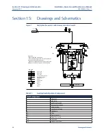
Drawings and Schematics
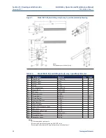
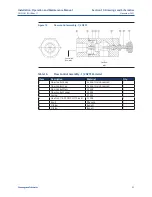
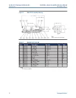
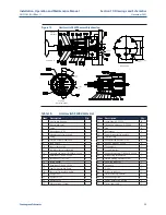
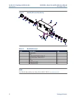
Figure 10
Model A324-DM-275_E switching relay (3-way, 2-position, N.C.)
assembly drawing
Table 14.
Model A324-DM-275_E switching relay (3-way, 2-position, N.C.) Parts List
Item
Description
Material
Qty.
Note
1
Diaphragm Assembly
Fairprene/TFE/CS
1
(Y)
10
Upper Body
AL 6061-T6
1
20
Plunger
PVC
1
(Y)
30
Diaphragm Cap
AL 6061-T6
1
40
"M" Lever
AL 6061-T6
1
50
Cylinder Plate
AL 6061-T6
1
70
Poppet, Lower
Nylon
1
(Y)
80
Poppet, Upper
Nylon
1
(Y)
90
Spring
SS 302
1
130
O-ring; Body
Nitrile
2
(Y)
140
O-ring; Poppet
Nitrile
2
(Y)
160
Capscrew, Operator
SS 304
1
170
Nut, Operator
SS 304
1
180
Capscrew, Cap
SS 304
6
190
Capscrew, Body
SS 304
4
191
High-Collar Lockwasher, Body
SS 18-8
4
200
Nut, Lever
SS 304
1
210
Roundheaded Push Bolt
SS 304
1
220
Poppet Spacer
SS 304
1
Notes:
-
(Y) Recommended spare parts
-
fasteners and maintenance tools are ANSI/INCH size
-
Recommended maximum 20 psig back pressure at exhaust port
Note:
Dimensions are in inches [mm]

