Installation, Operation and Maintenance Manual
DOC.IOM.RG.US Rev. 11
November 2021
21
Section 11: Operator Disassembly
Operator Disassembly
3.
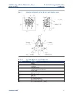
Connect flexible hoses to the ports of the cylinder to be repaired at the tee connection. Use
the handpump to cycle the operator to push the fluid out of the repair cylinder.
4.
Position the operator that the piston cap screw is against the end stop of the cylinder to
be repaired.
NOTE:
If necessary to remove all piping, fitting plugs/caps will need to be installed to prevent oil spills.
Cylinder disassembly
1.
Mark the cylinder parts for reinstallation on the same end and orientation of
the operator.
2.
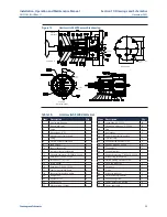
Remove stay rod nuts and end cap (it is not necessary to remove end stop and cover if no
seal is replaced).
3.
Remove some stay rods for access to cylinder and piston.
4.
Slide cylinder back off piston.
5.
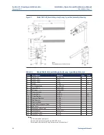
Remove piston cap screw, piston and seals.
6.
Remove cylinder plate ring, cylinder plate bolts and cylinder plate itself. Note the location
and number of seals.
7.
Remove drive rod seal (polypak) from cylinder plate.
NOTE:
There is no drive rod seal in the drive case, only a guide.
All pressure containing parts can now be inspected and replaced as necessary. It is a good practice
to replace all seals even if they appear serviceable. Proceed with cylinder assembly in Section 12,
unless complete disassembly is required.
Drive case disassembly
1.
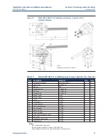
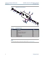
Remove 10 cover cap screws and lift off the drive case cover.
2.
Remove tanks, allowing entry to access hole for lower snap ring removal
if necessary.
3.
Remove the 2 drive pin snap rings, drive pin and rollers. Lift lower roller for best access to
lower snap ring (Series 3 and Series 6 drive pin with its lower snap ring is removed through
the access hole in bottom of drive case).
4.
Slide the drive rod out of the drive case, careful to avoid damage to the drive
rod surface.
5.
Lift out the yoke, upper and lower bushings, and bearings. Upper bushing may lift off with
the cover.
6.
Clean and inspect all parts; replace if necessary.

