background image

3

1.

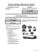
Unpack the items carefully to avoid damage to any
of the components.

Check to see that you have received the following
parts:

NOTE: If you are uncertain of part description,
refer to the exploded view illustration.

a. Fan motor assembly
b. One ceiling cover
c. One coupling cover
d. One motor cover
e. Three fan blade assemblies
f. One hanger bracket
g. One hanger ball/downrod assembly
h. One wall control parts bag
i. One loose parts bag, containing:

1. One clevis pin
2. One hairpin clip
3. Three wire connectors
4. Seven M6 x 12mm pan head blade screws
5. Seven blade M6 lockwashers
6. Four M5 x 10mm pan head screws
7. Four M5 external tooth lockwashers
8. Two 8-32 knurled nuts
9. Two #8 external tooth lockwashers

10. Two 8-32 x 1-1/4” threaded studs

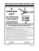
Model No.: ACF765

Tools Needed for Assembly

One Phillips head screwdriver
One stepladder
One wire stripper

The fan must be installed by a licensed electrician.

WARNING

This Manual Is Designed to Make it as Easy as Possible to

Assemble, Install, Operate and Maintain Your Ceiling Fan

Unpacking Instructions

For your convenience, check-off boxes are provided next to each step. As each step is completed, place a
check mark in the box. This will insure that all steps have been completed and will be helpful in finding
your place should you be interrupted.

Do  not  install  or  use  fan  if  any  part  is  damaged  or
missing, call:

1300 469 326

WARNING

!

NOTE:  Intermixing  blades  between  fans  can
cause  excessive  wobble.  Keep  blades  in  original
sets of three.

f

c

b

a

h

e

g

i

d

MATERIALS

Wiring,  outlet  box  and  box  connectors  must  be  of
type  required  by  the  local  code.  The  minimum  wire
would be a 3-conductor (2-wire with ground):

Содержание ACF765BQ

Страница 1: ... If separate speed control wall switch is used it must be an electronic type with suitable capacitor with characteristics similar to the following 470K Ohm 1 2 W 2uF 350Vac 3uF 350Vac For disconnection from the supply this fan MUST be provided with a switch with air gap contact separation in all active phase conductors and shall be incorporated in the fixed wiring according to the wiring rules Thi...

Страница 2: ... PLQLPXP UHFRPPHQGHG floor to fan blade clearance for a P FHLOLQJ 5 The fan PXVW be PRXQWHG with the fan blades at least 2 1 PHWHUV IURP the floor to prevent accidental contact with the fan blades 6 Your licensed electrician PXVW follow the UHFRPPHQGHG instructions for the proper PHWKRG of wiring your ceiling fan NOTE This fan is not suitable for use with solid state speed controls WARNING To redu...

Страница 3: ... 4 threaded studs Model No ACF765 Tools Needed for Assembly One Phillips head screwdriver One stepladder One wire stripper The fan must be installed by a licensed electrician WARNING This Manual Is Designed to Make it as Easy as Possible to Assemble Install Operate and Maintain Your Ceiling Fan Unpacking Instructions For your convenience check off boxes are provided next to each step As each step ...

Страница 4: ...Instructions CAUTION The blade assemblies must be mounted on the motor assembly so that the raised lip edge is facing up 1 Rotate the motor hub so the notched area is above the screw hole in the motor hub Install one blade assembly on the top of the motor assembly using two M6 x 12mm pan head screws and two M6 lockwashers supplied Figure 1 Repeat this procedure for the remaining two blade assembli...

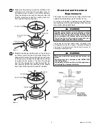
Страница 5: ...e 6 Electrical and Structural Requirements If your fan is to replace an existing ceiling light fixture turn electricity off at the main fuse box at this time and remove the existing light fixture The hanger bracket must be securely anchored and capable of withstanding a load of at least 31 Kg Turning off wall switch is not sufficient To avoid possible electrical shock be sure electricity is turned...

Страница 6: ...o ACF765 1 Securely attach the hanger bracket to the ceiling joist using the two screws supplied Figure 9 FLOOR CEILING AT LEAST 2 1 METER Figure 8 The fan must be hung with at least 2 1 meters of clearance from floor to blades Figure 8 WARNING The ceiling joist must be securely mounted and capable of supporting at least 31 Kg WARNING How To Hang Your Ceiling Fan 1 Securely connect the green yello...

Страница 7: ...h Return switched wire to ceiling fan to be connected to terminal 1 wall control switch 3 Fit wall control mechanism to the face plate and attach to wall THREADED STUDS 2 8 LOCKWASHER KNURLED KNOB CEILING COVER To avoid possible fire or shock make sure that the electrical wires are completely inside the outlet box and not pinched between the ceiling cover and the ceiling WARNING Figure 12 1 Screw ...

Страница 8: ... In the winter reverse the motor and operate the ceiling fan at low speed in the clockwise direction This produces a gentle updraft which forces warm air near the ceiling down into the occupied space Remember to adjust your AIRCON thermostat when using your ceiling fan additional energy and dollar savings could be realized with this simple step Turn Off When Not in the Room Ceiling fans cool peopl...

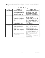
Страница 9: ...rs inside switch housing 4 Check to make sure wire connectors in switch r o r e h t o h c a e t s n i a g a g n i l t t a r t o n e r a g n i s u o h g n i l t t a r against the interior wall of the switch housing WARNING Make sure main power is turned OFF 5 Screws holding blades to flanges 5 Tighten screws securely are loose 3 Fan wobbles 1 Setscrew in motor coupling is loose 1 Tighten both setsc...

Страница 10: ...10 11 6 13 15 3 2 1 9 4 14 16 5 19 18 8 7 17 12 Repair Parts Model No ACF765 10 ...

Страница 11: ... m 0 1 x 5 M 1 t i K g n i c n a l a B 4 1 W W 4 0 8 3 6 7 S B 4 0 8 3 6 7 Q B 4 0 8 3 6 7 g n i l i e C r e v o C 5 1 W W 5 0 8 3 6 7 S B 5 0 8 3 6 7 Q B 5 0 8 3 6 7 g n i l p u o C r o t o M r e v o C 6 1 W W 6 0 8 3 6 7 S B 6 0 8 3 6 7 Q B 6 0 8 3 6 7 r e p p U g n i s u o H 7 1 1 1 8 3 6 7 1 1 8 3 6 7 1 1 8 3 6 7 g n i r i W s s e n r a H 8 1 W W 8 0 8 3 6 7 S B 8 0 8 3 6 7 Q B 8 0 8 3 6 7 3 f...

Отзывы: