background image

Device and COM Port Setup in Site SupervisorProgrammable Touchscreen Thermostat Setup for E2 and Site 
Supervisor • 37

5.

A window will appear. Press


and a confirmation will show 

MODBUS Device 

Address is set

.

NOTE: Refer to Section 3.2.1. to set the Device Address on the thermostat.

Site Supervisor 

4.4. Device and COM Port Setup in Site Supervisor

4.4.1. Modbus Device Setup

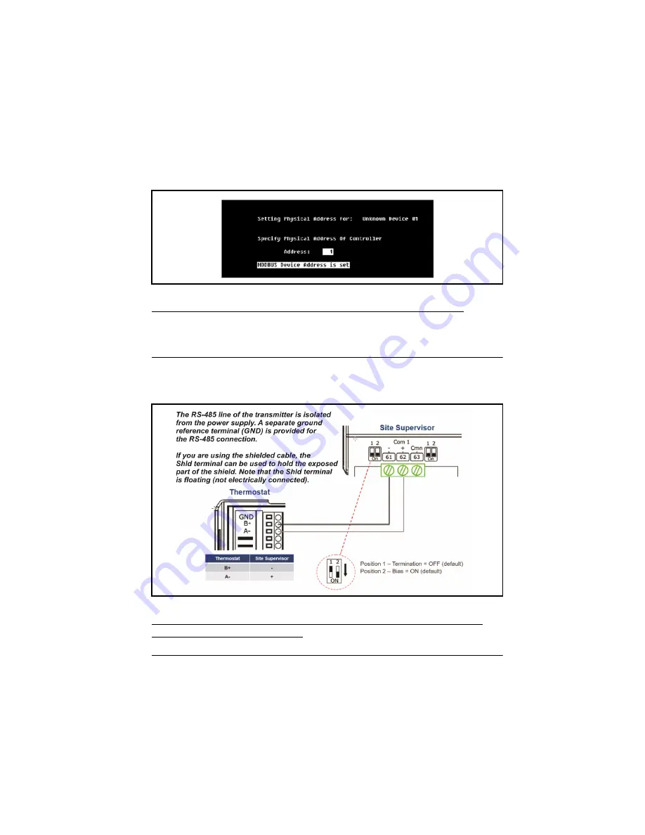
NOTE: The polarity of the MODBUS connection between Site Supervisor and 
Touchscreen Thermostat is reversed.

Figure 4-6

 - Modbus Device Address is Set

Figure 4-7

 - Modbus Device Setup for Site Supervisor

Содержание 810-1600

Страница 1: ...Emerson Programmable Touchscreen Thermostat Installation and Operation Manual 026 1739 Rev 0 ...

Страница 2: ......

Страница 3: ...Emerson 1065 Big Shanty Road NW Suite 100 Kennesaw GA 30144 USA 770 425 2724 www emerson com ...

Страница 4: ...ems 24VAC 7 2 4 6 Wiring Guide Heat Pump Systems 24VAC 8 3 OPERATION 9 3 1 GRAPHICAL USER INTERFACE GUI 9 3 2 CONFIGURATION MENU 9 3 2 1 Configuration Menu Modbus Device Address 10 3 2 2 Configuration Menu Modbus Device Baud Rate 11 3 2 3 Configuration Menu Thermostat System Configuration 11 3 2 4 Configuration Menu Full Segments Display Test 15 3 2 5 Configuration Menu System Revision Display 15 ...

Страница 5: ...ssor Min ON time 31 3 8 15 Compressor Min OFF time 31 4 PROGRAMMABLE TOUCHSCREEN THERMOSTAT SETUP FOR E2 AND SITE SUPERVISOR 32 4 1 NEW INSTALLATION OF DESCRIPTION FILE TO E2 32 4 1 1 Uploading the Touch_TStat Description File to E2 32 4 2 DEVICE AND COM PORT SETUP IN E2 34 4 2 1 Modbus Device Setup 34 4 2 2 E2 COM Port Setup 34 4 3 INSTALLING THE THERMOSTAT IN E2 36 4 3 1 Installing the Thermosta...

Страница 6: ... for 10K Ω NTC thermistor Modbus RTU on RS 485 9600 or 19200 bps default 2C 2H Fan ECO AUX O B Local integrated temperature sensor digital output I2C Conventional systems Heat pump systems 32 F to 122 F 0 C to 50 C 0 6 C 1 1 F within operating temperature range Default value is 4 F 2 C between cooling and heating 32 F to 122 F 0 C to 50 C 4 F to 140 F 20 C to 60 C 5 50 RH 77 F 25 C 0 to 95 Designe...

Страница 7: ...1 Y2 18 30VAC 50 60Hz 2 0A Y1 Cool Stage 1 relay output 18 30VAC 50 60Hz 1 0A Y2 Cool Stage 2 relay output 18 30VAC 50 60Hz 1 0A ECO Economizer relay output 18 30VAC 50 60Hz 1 0A G Fan Control relay output 18 30VAC 50 60Hz 1 0A GND Reference for DC Signals B RS 485 B Signal A RS 485 A Signal IN1 Remote 10K thermistor Indoor 0 3 3VDC 10K NTC IN2 Remote 10K thermistor Outdoor 0 3 3VDC 10K NTC IN3 Re...

Страница 8: ... relative humidity non condensing The thermostat should not be mounted Nearby a window on an outside wall or next to a door leading to the outside Where exposed to direct light and heat from any heat source such as a lamp the sun a fireplace or any heating element which may cause a false reading temperature measurement offset Nearby a direct airflow from supply registers air vent or duct outlet In...

Страница 9: ...ontacts pins terminal strips and terminal blocks that have to be separated during the operation To close the thermostat enclosure make sure to align the top and the bottom tabs between the front part and the baseplate and then push the front part firmly toward the wall Again some force is required to mate both parts 2 3 2 Mounting the Baseplate on the Wall Figure 2 2 Exploded View of Thermostat NO...

Страница 10: ...res and Electrical Connection Once the baseplate is affixed on the wall proceed with the wiring connections to the terminal block Please refer to Section 2 4 Wiring and Connections for configuration and signals definition CAUTION Do not over tighten the screws when attaching the baseplate on a wall as physical damage may occur CAUTION Keep the thermostat housing and vents clean and free of any deb...

Страница 11: ...gnals 2 4 3 Thermostat Input Terminals IN1 Remote 10K thermistor Indoor IN2 Remote 10K thermistor Outdoor IN3 Remote 10K thermistor Supply IN4 Remote Humidity sensor 0 5V IN5 Fan proof input GND Reference for DC Signals WARNING Turn off power of the HVAC system at the main power panel or on the controlled system itself to avoid any electrical shock or damage to the system Thermostat Power Table 2 ...

Страница 12: ...onomizer relay output AUX Dehumidification relay output 2 4 5 Wiring Guide Conventional Systems 24VAC Shorting Jumper R 24VAC Power Supply Rc 24VAC Power Supply for Y1 Y2 C 24VAC Power Supply Common Y1 Cool Stage 1 relay output Y2 Cool Stage 2 relay output W1 Heat Stage 1 relay output W2 Heat Stage 2 relay output G Fan Control relay output Thermostat Outputs Table 2 4 Output Terminals 2H 2C System...

Страница 13: ... left floating open 2 4 6 Wiring Guide Heat Pump Systems 24VAC Shorting Jumper R 24VAC Power Supply Rc 24VAC Power Supply for Y1 Y2 C 24VAC Power Supply Common Y1 Cool Stage 1 relay output Y2 Cool Stage 2 relay output O B Reversing Valve relay output G Fan Control relay output For systems with only one stage second stage terminal Y2 can be left floating open 2H 2C System with 2 Transformers Table ...

Страница 14: ...uch as room temperature and relative humidity The display is a resistive touch type that allows users to navigate and to change values that are shown on the display see Figure 3 1 3 2 Configuration Menu To access the Configuration Menu see Figure 3 2 press the icon for five 5 times within 15 seconds This step is to prevent unintentional access to the configuration menus Figure 3 1 Display With All...

Страница 15: ... display to indicate which parameter is being changed Ad stands for Address To change the value press either the up or down arrow and then press the check icon to go to the next parameter Press CA to cancel and exit the configuration menu without saving any changes 1 to 247 Range from 1 to 247 Figure 3 2 Configuration Menu Access Figure 3 3 Modbus Address Configuration Menu Address Number Modbus D...

Страница 16: ...ion menu see Figure 3 6 allows users to set the thermostat system configuration SC is shown on the right side of the display to indicate which parameter is being changed SC stands for System Configuration The current revision of the Emerson Programmable Touchscreen Thermostat supports Conventional HVAC Systems such as RTU and Heat pump Systems using a reversing valve There are 4x possible configur...

Страница 17: ...ready configured in RTU HP_O or HP_B only the IDLE and the current configuration are accessible through the menu NOTE The thermostat is always as a 2H 2C configuration system for both RTU and Heat Pump In the case the system has only 1 stage 1H 1C this configuration is inclusive within the 2 stages configuration In this case connect stage 1 terminals Y1 and W1 and leave stage 2 terminals floating ...

Страница 18: ...uration IMPORTANT Upon the first start of the thermostat the default System Configuration will be set to IDLE This means that the first step to get the device started is to configure the appropriate system configuration This menu will appear by default upon the first start See Figure 3 5 To access the configuration menu press the icon for five 5 times within 15 seconds Figure 3 5 Thermostat Displa...

Страница 19: ...ting the display will turn off for few seconds until reboot operation is completed Figure 3 7 Thermostat Display When Restarting to Occur Rebooting Figure 3 8 Thermostat System Configuration Menu New System Configuration Mode after IDLE IMPORTANT To change the current system configuration to a different one the operating system requires the system configuration is set to IDLE prior to the final co...

Страница 20: ... and last configuration menu see Figure 3 10 allows users to obtain the current system revision number This number is shown with 3 digits Note that there is no decimal after the first digit but the revision number contains the decimal point For example revision number 100 shown on the display means in fact 1 00 The software revision will be updated for the latest official release and will likely b...

Страница 21: ... 3 4 Time and Date Setting On the main display the clock at top right shows the actual time To change or update the time press the clock on the display see Figure 3 12 The first step in time settings is to set the time format between 12 hours AM PM or 24 hours Select between H12 for 12 hours AM PM and H24 for 24 hours format and then press the check icon to go to the next parameter see Figure 3 13...

Страница 22: ...d then press the check icon to go to the next parameter The last step see Figure 3 14 is the day of the week that will be flashing at the top of the screen To change the day of the week press either the up or down arrow to the desired value and then press the check mark to save the changes Press CA to cancel and return to the normal display without saving any changes IMPORTANT If time is set throu...

Страница 23: ...here on the screen Figure 3 16 Control icons will appear on both right and left side of the display The display will return to backlight off after about 30 seconds of inactivity on the touch display This backlight off state is essential to avoid important temperature measurement shifts due to thermostat self heating Figure 3 15 Main User Interface Backlight Off Figure 3 16 Wake up Display ...

Страница 24: ...ng setpoint press the desired setpoint on the right side of the display either COOL or HEAT see Figure 3 17 and the corresponding setpoint configuration menu will appear with arrows see Figure 3 18 Figure 3 17 Temperature Setpoint Access Figure 3 18 Temperature Setpoint Menu either COOL or HEAT ...

Страница 25: ...or marks see Section 3 5 4 Active Stage s Indicator Stages indicator marks will be displayed for the HEAT Mode the COOL Mode and the Fan Mode as well OFF Thermostat will be in OFF mode COOL Thermostat will be in cooling mode only HEAT Thermostat will be in heating mode only AUTO Thermostat will be in automatic switchover mode between cooling and heating mode 3 5 3 Fan Mode To change the Fan mode p...

Страница 26: ...mostat is in either cooling or heating mode Menus Interface Operation 21 3 5 4 Active Stage s Indicator The thermostat will show the mode is active with the number of activated output stages see Figure 3 21 as well as the target temperature setpoint under the given active mode Figure 3 20 Fan Mode Selection Fan Mode Description Table 3 6 Fan Mode Figure 3 21 Active Stage s Indicator ...

Страница 27: ...ng table 2 stage Configuration Cooling Heating 0 OFF 50 1 stage ON 100 2 stages ON 3 5 5 Fan Indicator The display will also show the output activation status for the fan see Figure 3 22 1 speed Fan Cooling Heating 0 OFF 100 1 speed ON Stages Configuration Output Activation Output Display on GUI Table 3 7 Active Stage Output Activation Status Figure 3 22 Fan Indicator Stages Configuration Output A...

Страница 28: ...ble and 0 to disable The scheduled operation Active can only be activated by the Modbus network If a Modbus communication to the thermostat occurs then it is assumed that there is a BMS with its own schedule that controls the thermostat In this case the internal schedule is on hold If the thermostat detects a Modbus communication loss no communication addressed to the thermostat during 10 minutes ...

Страница 29: ...UPIED 4 12 00 AM HEAT UNOCCUPIED 12 00 AM HEAT UNOCCIUPIED 3 5 7 Occupancy Mode Energy Saving Mode When the Schedule Mode is set to Follow there are two groups of temperature setpoints each one related to the occupancy status of the room A given room can be either configured to Occupied or Unoccupied for a certain period of time Normally the Occupied Mode has setpoints that are more comfortable fo...

Страница 30: ...ll occur if the internal schedule is running When a manual override has been set the icon Override will display see Figure 3 26 3 5 9 Screen Lock The touchscreen of the thermostat can be locked out to prevent any access to the settings for a user in front of the unit The Screen Lock function can only be set through the network and not the display of the thermostat Figure 3 25 Occupied Mode Icon on...

Страница 31: ... enclosure is open Switch 1 Pull up resistor enable PU This switch provides the ability to add a pull up resistor 510 Ohms on the RS 485 network for bias purposes Normally this switch is in the OFF position no pull up resistor on the network Switch 2 End of Line resistor enable EOL This switch provides the ability to add a termination resistor 120 Ohms on the RS 485 network for termination purpose...

Страница 32: ...nced Settings 3 8 1 Thermostat System Configuration Default Value IDLE The thermostat can control different types of HVAC equipment and is configured accordingly by the thermostat control configuration The supported types are Conventional Systems such as Rooftop Units RTU and Heat pump Systems HP To prevent any damage to the system upon first boot up sequence of the thermostat once installed the d...

Страница 33: ...URE Modbus registers Digital Local terminal connected to a digital switch Thermistor Local terminal connected to a thermistor 0 10V Local terminal connected to 0 10V voltage Input modes are configured to the following settings and are read only IN1 Thermistor used for the Indoor temperature IN2 Thermistor used for the Outdoor temperature IN3 Thermistor used for the Supply Air temperature Figure 3 ...

Страница 34: ...ing to a relationship between the thermostat internal temperature and the INPUT VALUE IN1 The formula used to get the value is WEIGHT x IN1 1 WEIGHT x Internal This register is used by the thermostat algorithm stage economizer display INPUT WEIGHT IN1 Value used in the CONTROL TEMPERATURE calculation 3 8 4 Dehumidification Mode When DEHUMIDIFICATION MODE is set to ON if the current humidity measur...

Страница 35: ... outputs a period of time before a transition from unoccupied to occupied This period is determined by the ECO PRE OCCUPANCY PURGE_PERIOD To allow the pre occupancy purge to be activated the following conditions must be reached The ECONOMIZER ENABLE must be enabled The scheduler must be enabled The ECO PRE OCCUPANCY PURGE_PERIOD must be different than OFF NOTE This parameter is set through network...

Страница 36: ...ault Value 15 C Minimum allowable temperature setpoint for a user NOTE This parameter is set through network and is not accessible on the display of the thermostat 3 8 12 Temperature Maximum Setpoint Default Value 25 C Maximum allowable temperature setpoint for a user 3 8 13 Temperature Stage Difference Default Value 1 C Temperature difference between engagement of stage 1 and stage 2 for both hea...

Страница 37: ... N 527 0729 to E2 Contact Customer Service to obtain this information Solutions CustomerService Emerson com NOTE Ultrasite32 Software must be installed to perform a description file upload 1 Connect to E2 using UltraSite32 refer to the UltraSite32 Manual P N 026 1002 2 Launch the UltraSite program and log in 3 Expand UltraSite to view Directory Level and Site Level see Figure 4 1 4 Right click Sit...

Страница 38: ...t dsc from the computer and click Open 8 Click Upload A window will display that the description file was successfully imported Click OK The description dsc file should appear in the list 9 Once completed disconnect from the E2 and reboot the E2 controller either manually with the toggle switch or remotely through Terminal Mode NOTE DO NOT omit the step of rebooting the controller Figure 4 1 Uploa...

Страница 39: ... 1739 Rev 0 4 2 Device and COM Port Setup in E2 4 2 1 Modbus Device Setup 4 2 2 E2 COM Port Setup 1 Log into the E2 by pressing 2 Press then and to access General controller Info 3 Press twice to move to C3 Serial tab Figure 4 4 Figure 4 3 E2 Network Connections ...

Страница 40: ...M6 5 Press for LOOK UP and select MODBUS 1 MODBUS 2 or MODBUS 3 6 Press to set configuration 7 Set the MODBUS connection as follows Press to select options and press e to set the configuration Com Baud 19 2 Kbaud Com Data Size 8 Com Parity None Com Port Stop Bits 1 Press to set the configuration 8 Press to save changes 9 Press to return to the Home screen Figure 4 4 C3 Serial Tab ...

Страница 41: ...ication Tch T Stat and enter the desired number of devices under Quantity up to 6 4 3 2 Commissioning the Thermostat 1 Press to enter the Network Summary screen 2 Highlight the Tch T Stat001 to be commissioned by pressing the down arrow and then 3 A window with Select Network appears on the screen select the Modbus number where you configured the device and press 4 Select the address for the devic...

Страница 42: ... Device Address is set NOTE Refer to Section 3 2 1 to set the Device Address on the thermostat Site Supervisor 4 4 Device and COM Port Setup in Site Supervisor 4 4 1 Modbus Device Setup NOTE The polarity of the MODBUS connection between Site Supervisor and Touchscreen Thermostat is reversed Figure 4 6 Modbus Device Address is Set Figure 4 7 Modbus Device Setup for Site Supervisor ...

Страница 43: ...ral System Properties 2 Select the Com Port the device is wired to Com Port 1 4 3 Select the available Modbus Modbus 01 Modbus 04 4 Set the Modbus connection as follows Com Port Baud 19 2 Kbaud Com Port data size 8 Com Port Parity None Com Port Stop Bits 1 5 Click Save to save the changes Figure 4 8 General System Properties Figure 4 9 Set Com Port Parameters ...

Страница 44: ...d Commissioning the Touchscreen Thermostat 1 Click the Port ID drop down list to select Modbus assigned to the Com Port selected in Section 4 4 3 2 Click the Address drop down list to select the Modbus Address default address is 1 3 Click the Association drop down list to select the HVACZone to associate with the thermostat 4 Click Update to save settings Figure 4 10 Add Controls Figure 4 11 Setti...

Страница 45: ...40 Emerson Programmable Touchscreen Thermostat I O Manual 026 1739 Rev 0 5 Wait a few seconds and the device should appear Online Figure 4 12 Device is Online ...

Страница 46: ...above 50 C or 122 F Heating or cooling system does not respond Set Thermostat Mode to HEAT and make sure the HEAT temperature setpoint is higher than the current room temperature Set Thermostat Mode to COOL and make sure the COOL temperature setpoint is lower than the current room temperature Open the thermostat enclosure as per Section 2 3 Thermostat Installation and wait 30 seconds prior to clos...

Страница 47: ...signed to provide reasonable protection against harmful interference in a residential installation This equipment generates uses and can radiate radio frequency energy and if not installed and used in accordance with the instructions may cause harmful interference to radio communications However there is no guarantee that interference will not occur in a particular installation If this equipment d...

Страница 48: ...r services described herein or their use or applicability Emerson Climate Technologies Retail Solutions Inc and or its affiliates collectively Emerson reserves the right to modify the designs or specifica tions of such products at any time without notice Emerson does not assume responsibility for the selection use or maintenance of any product Responsibility for proper selection use and maintenanc...

Отзывы: