Chapter 5 Software Operation 19
RDU-S Rack Data Unit User Manual
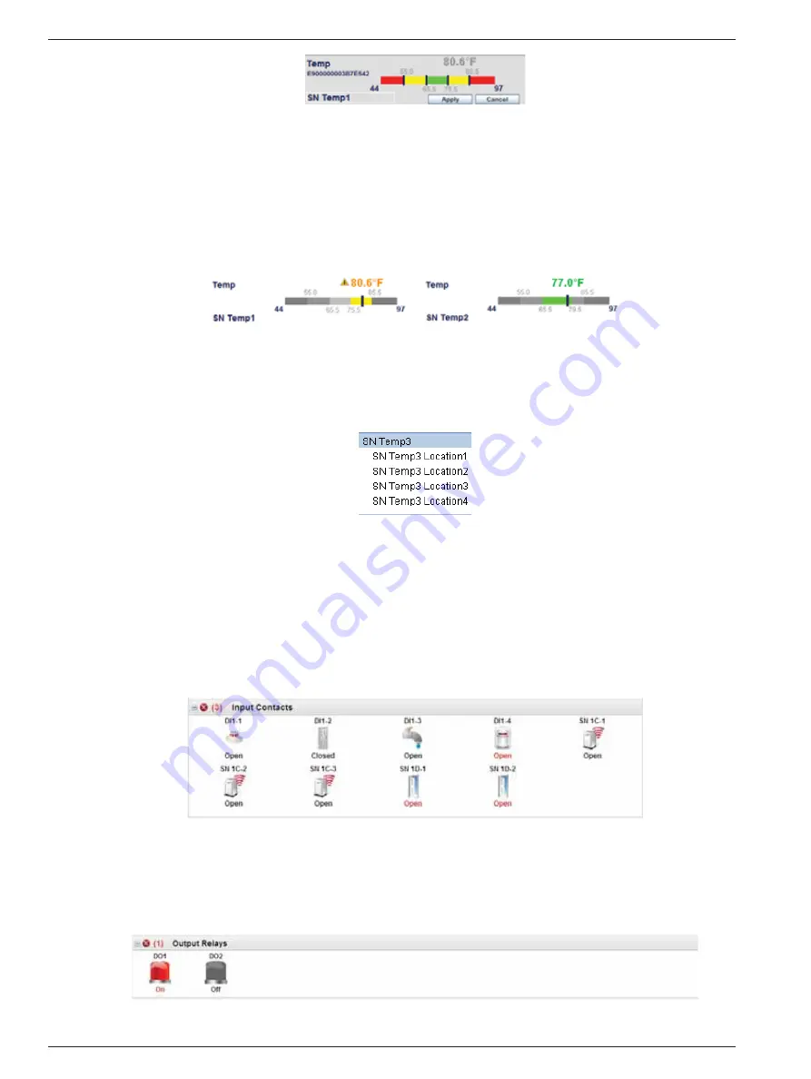
Figure 5-4 Setting mode of temperature sensor
3) Drag the mouse to set the high and low thresholds and double-click the sensor name (
‘
SN Temp1
’
shown in
Figure 5-4) to change it. The length of the sensor name is up to 10 characters.
The red, yellow and green areas on the histogram respectively indicate alarm, warning and normal range.
4) After setting, click
Apply
to confirm the setting.
Clicking
Cancel
will cancel the preceding setting.
If the temperature setpoint exceeds the normal range, the histogram will turn yellow or red; if it is within the normal
range, the histogram will turn green, as shown in Figure 5-5.
Warning status Normal status
Figure 5-5 Status figure after setting
2. Displaying sensor information
Move the mouse to one sensor histogram, and a prompt box, displaying sensor name and sensor location, will
appear, as shown in Figure 5-6.
Figure 5-6 Prompt box
Humidity sensor
The operation of the humidity sensor is the same as that of the temperature sensor.
Input contacts
Click the
Input Contacts
node in the
Monitor
structure tree, and the figure shown in Figure 5-7 will appear.
You can view the working status of the connected digital sensors. If the working status (
Open
or
Closed
) of the digital
sensor is displayed in black, it indicates that the digital sensor is normal and does not detect any alarm; if the working
status is displayed in red, it indicates that the digital sensor detects an alarm or alarms.
Figure 5-7 Input contacts window
Output relays
Click the
Output Relays
node in the
Monitor
structure tree, and the figure shown in Figure 5-8 will appear.
This window displays the working status of the devices connected to the relay port. For example, the icon of
DO1
(indicator alarm) turning red indicates that it generates an alarm.
Figure 5-8 Output relays window
Содержание RDU-S
Страница 2: ......


