


Chapter:
Connectors
LCD
page 22 embedded-logic
PB945+
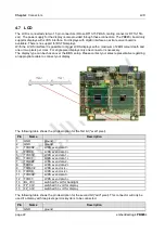
4.7 LCD
The LCD is connected via two 15 pin connectors (Hirose DF13-15P-DAS, mating connector: DF13-15S-
xxx). The power supply for the display is also provided through these connectors. The PB945+ board only
supports displays with LVDS interface. For displays with digital interface an extra receiver board is
available. There is no support for DSTN displays.
With the LVDS interface it is possible to trigger LVDS displays with a maximum of 24Bit colour depth and
one or two pixels per clock. For single pixel displays only one connector is necessary.
The display type can be chosen over the BIOS setup. Please contact your sales representative regarding
an appropriate cable to connect your display.
The following table shows the pin description for the first bit ("even" pixel).
Pin
Name
Description
1
GND
ground
2
GND
ground
3
TXO00#
LVDS even data 0 -
4
TXO00
LVDS even data 0 +
5
TXO01#
LVDS even data 1 -
6
TXO01
LVDS even data 1 +
7
TXO02#
LVDS even data 2 -
8
TXO02
LVDS even data 2 +
9
TXO0C#
LVDS even clock -
10
TXO0C
LVDS even clock +
11
TXO03#
LVDS even data 3 -
12
TXO03
LVDS even data 3 +
13
BL_VCC
switched 5 volt for backlight
14
FP_3.3V
switched 3.3 volt for display
15
FP_3.3V
switched 3.3 volt for display
The following table shows the pin description for the second bit ("odd" pixel). This connector will only be
used if a display with two pixels per clockcycle is to be connected.
Pin
Name
Description
1
GND
ground


