


Chapter:
Connectors
PC/104-Plus Bus
page 18 embedded-logic
PB945+
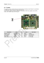
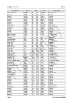
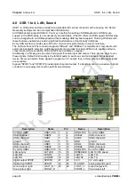
4.4 PC/104-Plus Bus
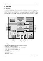
Expansion cards can be connected to the board using the PC/104-Plus connector. A maximum of four
PC/104-Plus cards are supported.
The interrupt routing and the IDSEL signals for the expansion cards are specified in the PC/104-Plus
specification.
Description
Name
Pin
Name
Description
ground
GND
A1
B1
N/C
reserved
5 volt - IO buffer power
VCCIO
A2
B2
AD2
PCI – address/data 2
PCI – address/data 5
AD5
A3
B3
GND
ground
PCI – com/byte enable 0
CBE0#
A4
B4
AD7
PCI – address/data 7
ground
GND
A5
B5
AD9
PCI – address/data 9
PCI – address/data 11
AD11
A6
B6
VCCIO
5 volt - IO buffer power
PCI – address/data 14
AD14
A7
B7
AD13
PCI – address/data 13
3.3 volt supply
3.3V
A8
B8
CBE1#
PCI – com/byte enable 1
PCI – system error
SERR#
A9
B9
GND
ground
ground
GND
A10
B10
PERR#
PCI – parity error
PCI – stop
stop#
A11
B11
3.3V
3.3 volt supply
3.3 volt supply
3.3V
A12
B12
TRDY#
PCI – target ready
PCI – frame
FRAME#
A13
B13
GND
ground
ground
GND
A14
B14
AD16
PCI – address/data 16
PCI – address/data 18
AD18
A15
B15
3.3V
3.3 volt supply
PCI – address/data 21
AD21
A16
B16
AD20
PCI – address/data 20
3.3 volt supply
3.3V
A17
B17
AD23
PCI – address/data 23
PCI – ID select slot 1
IDSEL0
A18
B18
GND
ground
PCI – address/data 24
AD24
A19
B19
CBE3#
PCI – com/byte enable 3
ground
GND
A20
B20
AD26
PCI – address/data 26
PCI – address/data 29
AD29
A21
B21
VCC
5 volt supply
5 volt supply
VCC
A22
B22
AD30
PCI – address/data 30
PCI – bus request slot 1
REQ0#
A23
B23
GND
ground
ground
GND
A24
B24
REQ2#
PCI – bus request slot 3
PCI – bus grant slot 4
GNT1#
A25
B25
VCCIO
5 volt - IO buffer power
5 volt supply
VCC
A26
B26
CLK0
PCI – clock slot 1


