


DC/DC Converter
PSC30
User Manual
Page 17 (24)
©2009. ELTEK VALERE DEUTSCHLAND GmbH.
UM_PSC30_E_EVD_2011-01-19.doc
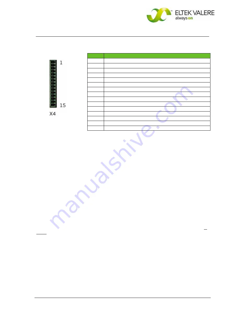
Pin assignment of
X4
for PSC30/220V with
CAN-Bus
(without signalling relay)
LEGEND:
1)
tri-state-input:
pin 8 on -V
O
=
discharge test mode
pin 8 on +U
A
=
boost charge mode
Note:
For 220V units: For the connection to +Vo an additional series resistor has to be used
(220V: 150kOhm).
2)
connection of temperature sensor with 2pole wire to pin 9(+) and pin 7 (-)
Note:
If several modules are in paralleling then the pin 7 from every unit has to closed.
3)
At active current sharing mode of paralleling units the pin 10 of every module has to be connected
together. The Analog – GND (pin 7) has to be connected too.
ATTENTION!
If active current sharing mode is enabled, the use of external decoupling diodes and fuses as well in
minus on the output side are
not
allowed.
4)
External switch ON/Off with optocouppler: internal resistor 2.7kOhm, I
min
5 mA, I
max
= 10 mA
Note:
The input is free of potential with saved electrical decoupling to primary side and with 500V DC to
secondary side.
5)
The relay outputs are free of potential with saved electrical
decoupling to primary side and with 500V DC to secondary side.
X4
, pin Function
1
(
+
) external switch on/off
4
)
2
(
-
) external switch on/off
3
optocoupler emitter
4
optocoupler collector "Mains O.K."
5
optocoupler collector "VO O.K."
6
optocoupler collector "IO"
7
BUS – GND
8
signal input discharge test mode / boost charge mode
1
)
9
temperature sensor (+)
2
)
10
control wire for current sharing mode
3
)
11
CVCC
+
12
CAN-H
13
CAN-L
14
CVSS
-
15
Not connected


