www.elpro.com.au
245U-E Wireless Ethernet Modem User Manual
17
Rev Version 2.24
The power requirements of the 245U-E unit are shown in the following table.
245U-E-G
245U-E-A
Voltage
12 Vdc
24 Vdc
12 Vdc
24 Vdc
Quiescent
290 mA
150 mA
300 mA
160 mA
TX @100 mW
310 mA
170 mA
370 mA
190 mA
TX @ 400 mW
340 mA
180 mA
410 mA
210 mA
A ground terminal is provided on the back of the module. This terminal should be connected to the main
ground point of the installation in order to provide efficient surge protection for the module (refer to the
installation diagram in the
245U-E Installation Guide).
2.3 Serial Connections
RS232 Serial Port
The serial port is a 9-pin DB9 female, and provides for connection to a host device as well as a PC terminal
for configuration, field testing, and factory testing. Communication is via standard RS232 signals. The
245U-E is configured as DCE equipment with the pinouts described below.
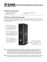
Hardware handshaking using the CTS/RTS lines is provided. The CTS/RTS lines may be used to reflect the
status of the local unit’s input buffer. The 245U-E does not support XON/XOFF. Example cable drawings for
connection to a DTE host (a PC) or another DCE hosts (or modem) are detailed in Figure 14.
Figure 14 Serial Cable
DB9 Connector Pinouts
Pin
Name
Direction
Function
1
DCD
Out
Data Carrier Detect
2
RD
Out
Transmit Data – Serial Data Output (from DCE to DTE)
3
TD
In
Receive Data – Serial Data Input (from DTE to DCE)
4
DTR
In
Data Terminal Ready
5
SG
—
Signal Ground
6
DSR
Out
Data Set Ready - always high when unit is powered on.
7
RTS
In
Request to Send
8
CTS
Out
Clear to Send
9
RI
Ring Indicator