DS80SC60-001 LBT80336 IS7525-AA
I
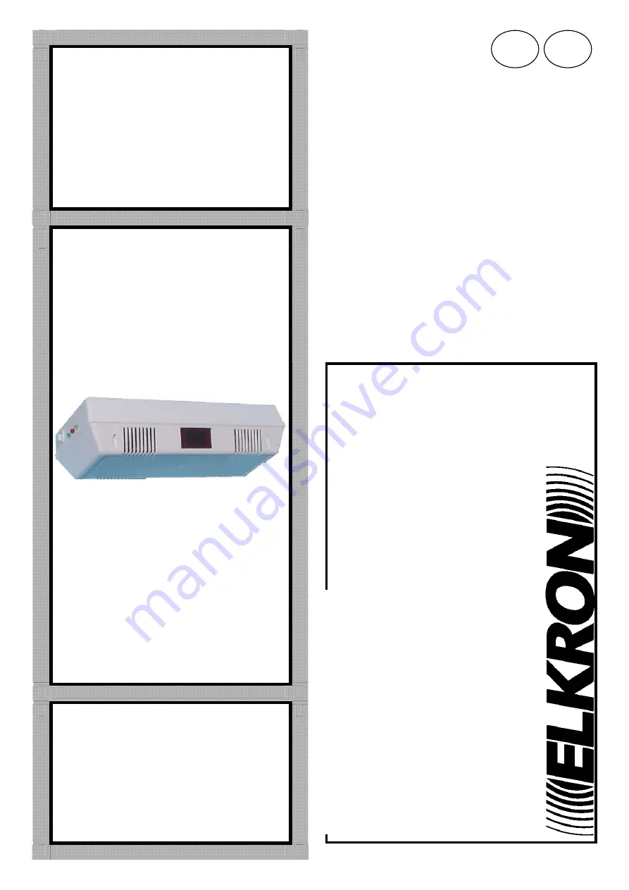
Manuale di installazione
Installation Manual
C302
Centralina monozona Single zone control panel
GB
Страница 1: ...DS80SC60 001 LBT80336 IS7525 AA I Manuale di installazione Installation Manual C302 Centralina monozona Single zone control panel GB ...
Страница 2: ...l caso in cui il computer non soddisfi ai requisiti minimi richiesti oppure il programma di visualizzazione mappe venga utilizzato unitamente ad altri programmi non di sistema giochi Internet animazioni COPYRIGHT This software is produced by ELKRON S p A and is protected by Italian copyright laws and by all other applicable national laws Therefore this software like all other material such as book...
Страница 3: ...elatori di gas 12 7 7 Collegamento ad RG54 Un dispositivo 13 7 8 Collegamento ad RG54 2 o più dispositivi 13 Index 1 General Information 14 2 Operation 15 3 Dimensions and drilling template 16 4 Specifications 17 5 Card and terminal board description 20 5 1 Jumper description 19 6 Installation 19 7 Control panel connection 22 7 1 Indicative connecting diagrams 20 7 2 Standard system with E 401 E 4...
Страница 4: ...ado di alimentare e pilotare n 6 Elettromagneti per il blocco delle porte una uscita dedicata controlla e gestisce al meglio le batterie per il sostenimento in caso di mancanza della fonte primaria di alimentazione La Rivelazione doppia della Centralina permette di controllare in modo idoneo i due parametri di un incendio FUMO e CALORE La Rivelazione interna della Centralina per l incendio è deleg...
Страница 5: ...one 1 o dal reset esterno morsetto n 12 In caso di allarme e ritardo sgancio Elettromagneti con tempo di La Centralina toglie alimentazione agli Elettromagneti in funzione al tempo selezionato mentre immediatamente eccita il relè di Allarme accende il Led Rosso la Lampada ed il buzzer funzionano in modo oscillante per indicare che il Timer è in funzione scaduto il tempo la lampada ed il buzzer si ...
Страница 6: ...e il Led di Fault ed il buzzer funzionano in modo oscillante Acceso Funzionamento della Centralina a seguito di un bip dopo 4 secondi Led Verde Spento Centralina con Elettromagneti e Linea di Rivelazione esclusi Led Rosso Acceso fisso Presenza di allarme Spento Linea Rivelazione Corretta Lampeggiante Linea Rivelazione non Terminata buzzer intermittente Led Giallo Acceso Led verde spento Linea Rive...
Страница 7: ...amento 10 C 50 C Contatti relè scambio libero di allarme 1A max 30 VDC Uscita batterie tampone N 2 Batterie da 12 V max 1 2 Ah Corrente di ricarica batterie 120 mA Materiale del contenitore ABS autoestinguente UL94 V0 Colore RAL 7032 Misure mm 283 L 113 P 71 H Peso 700 g Grado di protezione IP 32 NOTE A monte dell apparecchio collegare un interruttore magneto termico differenziale Per garantire la...
Страница 8: ...va di allarme max 100 mA E Negativo Elettromagneti E Positivo Elettromagneti max 300 mA RP Rip negativa anomalia porta max 100 mA LR Positivo linea di rivelazione max 80 mA LR Negativo linea di rivelazione RE Ingresso positivo Reset 27 Positivo 27 VDC campo max 300 mA NA Contatto NA relè allarme 1 A 30VDC C Contatto C relè allarme 1 A 30VDC NC Contatto NC relè allarme 1 A 30VDC SP Segnale porta F1...
Страница 9: ...igura a lato Per ambienti di altezze superiori a 6 metri ma non superiori ai 12 metri si deve prevedere l utilizzo di un rivelatore esterno collegato alla centrale C 302 ed installato sulla copertura La centrale C 302 dovrà essere installata ad un altezza pari alla metà dell altezza della copertura soffitto distanziandola 1 metro dalla parete in cui sia presente la porta di ingresso In tale caso d...
Страница 10: ...ativi RE SP LD2 LD3 LD1 RP 1 BT BT NC 27 LR LR E N F RA E NA C F2 F1 M1 M2 Trasformatore Buzzer 5 3 1 J2 4 2 6 000085 230 V 50 Hz ELETTROMAGNETI SIRENA RIVELATORI 24 V d c 300 mA Max 13 1 6 7 8 Rip Neg anomalia porta 3 4 1 2 5 24 V d c Contatti NC posizionati sulle porte ...
Страница 11: ...a mod C 302 7 3 Impianto tipo con elettromagneti E 401 E 402 con contatti chiusi per il controllo porte RIVELATORE Centralina mod C 302 Elettromagnete mod E 402 Contatti NC per il controllo porta 7 4 Impianto tipo con elettromagneti E 405 per il controllo dello sgancio porta RIVELATORE Elettromagnete mod E 405 Centralina mod C 302 ...
Страница 12: ...ssa in parallelo come rappresentato dal disegno 7 6 Collegamenti a rivelatori di gas LR 27 LR 3 4 1 2 5 3 6 5 4 2 1 LR 27 LR 7 6 1 8 LR 27 LR Schema di collegamento con rivelatore di GAS RG 201 o RG 203IP Max 2 Schema di collegamento con rivelatore di GAS RG 203 Max 2 Schema di collegamento con rivelatore di GAS BPG 213 Max 2 Resistenza di Fine Linea da 3 3 Kohm Resistenza di Fine Linea da 3 3 Koh...
Страница 13: ... 5 7 10 9 Passacavo P7 ON P8 ON 7 8 Collegamento ad RG54 2 o più dispositivi Il numero massimo di sensori RG54 collegabili è di 3 M1 000088 N 1 F1 F2 F BT BT RA E E RP J2 Buzzer 2 1 6 4 3 5 NA RE LR 27 NC C SP 6 3 1 2 4 5 Sezione cavi 1mm2 Terra locale 10 8 7 9 Passacavo M2 LR Trasformatore 2 1 7 4 3 5 6 9 8 10 Primo sensore P7 ON P8 ON Ultimo sensore P7 ON P8 ON 3K3 Resistenza di fine linea ...
Страница 14: ... with 30 s delay after alarm notification alarm notification continues to be active During the time delay alarm notification appliances audible and visible are activated in pulsive way at the end of countdown the door holders are unlock and alarm notification appliances switch to steady way C 302 is able to supply and control up to 6 Door holder for the door lock a dedicated output supervise the e...
Страница 15: ...om the Internal heat Detection is stored To restore the nornal operation switch the reset button to 1 position or switch the external reset button connected to terminal 12 If an alarm condition occurs with time delay set the FIRE windows the red led and buzzer operate ina pulsive way till the delay time comes to 0 at that time door holders are unlocked and notifications devices turn in a steady wa...
Страница 16: ... indication and the lamp are permanently alight and the Fault Led and the Buzzer operate discontinuously Alight Control Panel Operation following a beep after 4 seconds Green Led Off Control Panel with door holders and Detection Line excluded Red Led Permanently alight Alarm condition Off Detection Line Corrected Flashing Detection Line not Completed buzzer sounds in pulsive way Yellow Led Alight ...
Страница 17: ...zer Working temperature 10 C 50 C Alarm free exchange relay contacts 1A max 30 VDC Battery 2 Batteries of 12 V max 1 2 Ah Battery recharging current 120 mA Casing material ABS self extinguishing UL94 V0 Colour RAL 7032 Sizes mm 283 L 113 P 71 H Weight 700 g Protection degree IP 32 NOTES Connect a residual thermal magnetic circuit breaker upstream of the appliance To ensure the appliance protection...
Страница 18: ...tive input RA Negative Alarm Rep max 100 mA E Electromagnet Negative E Electromagnet Positive max 300 mA RP Door fault negative Rep max 100 mA LR Detection line positive max 80 mA LR Detection line negative RE Reset positive input 27 Positive 27 VDC field max 300 mA NA Alarm relay NA contact 1 A 30VDC C Alarm relay C contact 1 A 30VDC NC Alarm relay NC contact 1 A 30VDC SP Door signal F1 Protectio...
Страница 19: ...or environments over 6 metres tall but not greater than 12 metres use an external detector which is connected to the C 302 control module and installed on the ceiling The C 302 control panel shall be installed at a height equal to half of the covering ceiling height leaving a space of 1 metre from the wall on which the front door is present In such case use an appropriate bracketing to secure the ...
Страница 20: ... N F RA E NA C F2 F1 M1 M2 Trasformatore Buzzer 5 3 1 J2 4 2 6 000085 230 V 50 Hz ELETTROMAGNETI DOOR HOLDER SIRENA SIREN RIVELATORI 24 V d c 300 mA Max 13 1 6 7 8 Rip Neg anomalia porta 3 4 1 2 5 24 V d c Contatti NC posizionati sulle porte Trasformer DETECTORS NC Contacts positioned on the doors Door fault Neg Rep ...
Страница 21: ...2 Door Holder Detector C 302 7 3 Standard system with E 401 E 402 electromagnets with closed contacts for the door check C 302 E 402 Door Holder Detector NC contact for doors check 7 4 Standard system with E 405 electromagnets for the door release check C 302 Detector E 405 Door Holder ...
Страница 22: ...h button The electromagnet line must be parallel connected as shown in the drawing E 405 E 405 Door holder SP RP E E C 302 This electromagnet is equipped with a release push button A reed contact is used for release control The electromagnet line must be parallel connected as shown in the drawing 7 6 Connections to gas detectors ...
Страница 23: ...nd Cable gland 7 8 Connection to RG54 two or more devices You can connect up to 3 RG54 sensors NA RE LR 27 NC C SP 6 3 1 2 4 5 Sezione cavi 1mm2 1mm2 Wire cross section Terra locale 10 8 7 9 Passacavo Cable gland M2 LR Trasformatore M1 000088 N 1 F1 F2 F BT BT RA E E RP J2 Buzzer 2 1 6 4 3 5 2 1 7 4 3 5 6 9 8 10 Primo sensore First device P7 ON P8 ON Ultimo sensore Last device P7 ON P8 ON 3K3 Resi...
Страница 24: ...RON S p A Via Cimarosa 39 10154 Torino TO Italy Tel 39 0 11 3986711 Fax 39 0 11 3986790 Sede Milano Via Gadames 109 20151 Mi Italy Tel 39 0 2 334491 Fax 39 0 2 33449213 www elkron it mail to info elkron it ...