SINUS PENTA
PENTA MARINE
IRIS BLUE
STO FUNCTION
APPLICATION MANUAL
14/
27
All the Sinus Penta, Penta Marine and Iris Blue drives are equipped with the same ES927 control board.
Figure 7,
Figure 8 and
Figure 9 show the relevant components related to the STO function.
In particular, Figure 7 shows the diagnostic display and the ENABLE-A and ENABLE-B terminals
locations, while
Figure 8 and
Figure 9 show the details of the terminals and the diagnostic LEDs indicators.
The diagnostic test procedure, covered in the following sections, refers to those LEDs indicators.
3. DEFINITION OF THE SYSTEM
3.1. System Structure
The STO function operates in the CPU & CONTROL LOGIC board called ES927.
When both STO inputs are energized, the STO function is on standby and the drive operates normally.
The STO function is active (motor stopped) when one of the two inputs is de-energized: if at least one of
the STO inputs is de-energized, the STO function is active and stops the drive; the drive can start only
after the STO inputs have been energized and the drive faults (if any) have been reset.
CAUTION
The STO function is based on a dual channel hardware implementation. To
achieve the rated protection level guaranteed by ES927 board, both the
ENABLE-A and ENABLE-B shall be de-energized to obtain the STO function.
3.2. Functional Description
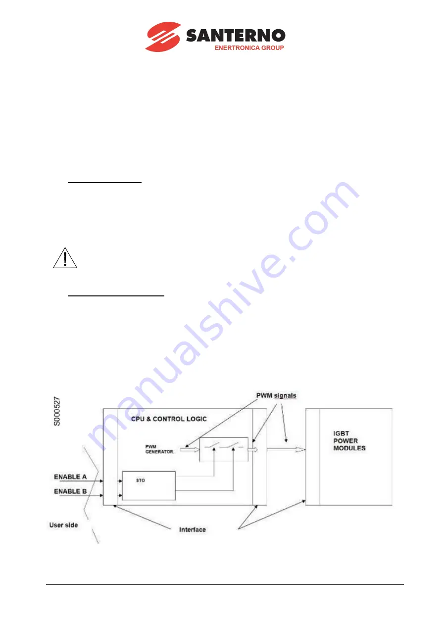
The motor stop is obtained by cutting the PWM signals from the CPU to the IGBT Drivers. This cut is
made with two series-connected, 3-state buffers: both buffers must be enabled to allow transferring the
PWM signals to the IGBTs.
The enable signals (ENABLE-A and ENABLE-B) come from the two separate channels that process
independently the external demand.
The motor can work only if both channels send the Enable signal, while if only one Enable signal is
removed, the motor is stopped.
Figure 10 shows the block diagram of the integration of the STO function into the Sinus Penta, Penta
Marine and Iris Blue drives.
Figure 10
– Integration of the STO function into the drives


