5.3 Connection example VariEco L RH
230 V / 50 Hz
Temperature limiter
Junction box
Capacitor
Final limit
switch
Motor cable
plug
Switch box
Mains 230 V/50 Hz
black
brown
blue
green/yellow
Fig. 4 Diagram VariEco L RH 230 V / 50 Hz
Check for functioning: If necessary, change or swap the
assignment of the direction buttons for the operating
switch/push button.
Important
The motor controls in up/down direction must be locked
against each other.
The motor controls in the OPEN and DOWN/CLOSE travel
directions must be locked against each other. A reversing
delay of at least 0.5 seconds must be ensured.
Due to reverse voltage from the installed capacitor, never
connect several drives in parallel.
5.4 Adjustment of the end positions
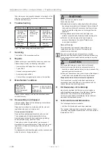
8 turns of one of the two limit switch setting screws
corresponds to 1 turn of the winding shaft.
Turning the limit switch position setting screw from negative
to positive causes the travel path of the blind to increase
[positive (+) = greater travel path of blind].
Important
The two interior limit switch setting screws for the upper
and lower end positions are assigned based on the parallel
position of the rotating crown to the limit switch with the
printed running direction arrow.
Before readjusting an end position, move the blind out of
the correct position with [OPEN ▲] and [DOWN/CLOSE ▼].
For activation of the limit switch setting screws, use the
setting tool (Item No. 131096401) or a hexagon socket tool.
Never use an electric screwdriver!
Blind in front of the winding shaft
1
2
3
4
5
6
A
B
C
D
7
8
E
F
1
2
3
4
5
6
7
8
A
B
C
D
E
F
-
336699333300110011
369330101.asm
05.03.2019
fleischerd
-
VVaarriiEEccoo LL 6600 RRHH
1:20
-
Diese Maße werden besonders geprüft
This dimensions are particularly examined
Gratfrei
burr-free
Allgemeintoleranzen
General Tolerances:
DIN ISO 2768-1 m-E
DIN ISO 2768-2 K-E
Maßstab / Scale:
Werkstoff / Material:
Datum / Date:
Name:
A-EW
geprüft
proofed:
Benennung / Title:
Zeichnungsnummer / Drawingnumber:
Werkzeug-Nr
Tool-Number:
GGeemmääß
ß RRooHHSS--RRiicchhttlliinniiee 22001111//6655 EEGG // aaccccoorrddiinngg ttoo RRooHHSS ddiirreeccttiivvee 220000//1111//EEUU
Index:
Kurzbeschreibung / Short Comment:
Name:
Datum / Date:
elero GmbH
Antriebstechnik
Maybachstr. 30, D-73278 Schlierbach
Fon: (0049) 7021 / 9539-0
Fax: (0049) 7021 / 9539-212
Verwendung , Kennzeichnung / Used in, Spezification:
Gewicht / weight:
Solid Edge
-
-
-
-
-
-
-
-
-
-
-
-
-
-
-
-
-
-
-
-
-
-
-
-
-
-
-
-
-
-
-
-
-
-
1
CAD-Nr / CAD-No:
DIN A4
Format / format:
rev. Nr.
-
Lieferantenkennzeichnung nach Absprache
Supplier ID according to prior agreement
4,728 kg
01
Reg. Nr
-
-
-
-
-
-
-
-
-
1
2
3
4
5
6
A
B
C
D
7
8
E
F
1
2
3
4
5
6
7
8
A
B
C
D
E
F
-
336699333300110011
369330101.asm
05.03.2019
fleischerd
-
VVaarriiEEccoo LL 6600 RRHH
1:20
-
Diese Maße werden besonders geprüft
This dimensions are particularly examined
Gratfrei
burr-free
Allgemeintoleranzen
General Tolerances:
DIN ISO 2768-1 m-E
DIN ISO 2768-2 K-E
Maßstab / Scale:
Werkstoff / Material:
Datum / Date:
Name:
A-EW
geprüft
proofed:
Benennung / Title:
Zeichnungsnummer / Drawingnumber:
Werkzeug-Nr
Tool-Number:
GGeemmääß
ß RRooHHSS--RRiicchhttlliinniiee 22001111//6655 EEGG // aaccccoorrddiinngg ttoo RRooHHSS ddiirreeccttiivvee 220000//1111//EEUU
Index:
Kurzbeschreibung / Short Comment:
Name:
Datum / Date:
elero GmbH
Antriebstechnik
Maybachstr. 30, D-73278 Schlierbach
Fon: (0049) 7021 / 9539-0
Fax: (0049) 7021 / 9539-212
Verwendung , Kennzeichnung / Used in, Spezification:
Gewicht / weight:
Solid Edge
-
-
-
-
-
-
-
-
-
-
-
-
-
-
-
-
-
-
-
-
-
-
-
-
-
-
-
-
-
-
-
-
-
-
1
CAD-Nr / CAD-No:
DIN A4
Format / format:
rev. Nr.
-
Lieferantenkennzeichnung nach Absprache
Supplier ID according to prior agreement
4,728 kg
01
Reg. Nr
-
-
-
-
-
-
-
-
-
Blind in front of the winding shaft
Top end position:
white setting screw
Bottom end position:
orange setting screw
Top end position:
orange setting screw
Bottom end position:
white setting screw
Blind behind the winding shaft
1
2
3
4
5
6
A
B
C
D
7
8
E
F
1
2
3
4
5
6
7
8
A
B
C
D
E
F
-
336699333300110011
369330101.asm
05.03.2019
fleischerd
-
VVaarriiEEccoo LL 6600 RRHH
1:20
-
Diese Maße werden besonders geprüft
This dimensions are particularly examined
Gratfrei
burr-free
Allgemeintoleranzen
General Tolerances:
DIN ISO 2768-1 m-E
DIN ISO 2768-2 K-E
Maßstab / Scale:
Werkstoff / Material:
Datum / Date:
Name:
A-EW
geprüft
proofed:
Benennung / Title:
Zeichnungsnummer / Drawingnumber:
Werkzeug-Nr
Tool-Number:
GGeemmääß
ß RRooHHSS--RRiicchhttlliinniiee 22001111//6655 EEGG // aaccccoorrddiinngg ttoo RRooHHSS ddiirreeccttiivvee 220000//1111//EEUU
Index:
Kurzbeschreibung / Short Comment:
Name:
Datum / Date:
elero GmbH
Antriebstechnik
Maybachstr. 30, D-73278 Schlierbach
Fon: (0049) 7021 / 9539-0
Fax: (0049) 7021 / 9539-212
Verwendung , Kennzeichnung / Used in, Spezification:
Gewicht / weight:
Solid Edge
-
-
-
-
-
-
-
-
-
-
-
-
-
-
-
-
-
-
-
-
-
-
-
-
-
-
-
-
-
-
-
-
-
-
1
CAD-Nr / CAD-No:
DIN A4
Format / format:
rev. Nr.
-
Lieferantenkennzeichnung nach Absprache
Supplier ID according to prior agreement
4,728 kg
01
Reg. Nr
-
-
-
-
-
-
-
-
-
1
2
3
4
5
6
A
B
C
D
7
8
E
F
1
2
3
4
5
6
7
8
A
B
C
D
E
F
-
336699333300110011
369330101.asm
05.03.2019
fleischerd
-
VVaarriiEEccoo LL 6600 RRHH
1:20
-
Diese Maße werden besonders geprüft
This dimensions are particularly examined
Gratfrei
burr-free
Allgemeintoleranzen
General Tolerances:
DIN ISO 2768-1 m-E
DIN ISO 2768-2 K-E
Maßstab / Scale:
Werkstoff / Material:
Datum / Date:
Name:
A-EW
geprüft
proofed:
Benennung / Title:
Zeichnungsnummer / Drawingnumber:
Werkzeug-Nr
Tool-Number:
GGeemmääß
ß RRooHHSS--RRiicchhttlliinniiee 22001111//6655 EEGG // aaccccoorrddiinngg ttoo RRooHHSS ddiirreeccttiivvee 220000//1111//EEUU
Index:
Kurzbeschreibung / Short Comment:
Name:
Datum / Date:
elero GmbH
Antriebstechnik
Maybachstr. 30, D-73278 Schlierbach
Fon: (0049) 7021 / 9539-0
Fax: (0049) 7021 / 9539-212
Verwendung , Kennzeichnung / Used in, Spezification:
Gewicht / weight:
Solid Edge
-
-
-
-
-
-
-
-
-
-
-
-
-
-
-
-
-
-
-
-
-
-
-
-
-
-
-
-
-
-
-
-
-
-
1
CAD-Nr / CAD-No:
DIN A4
Format / format:
rev. Nr.
-
Lieferantenkennzeichnung nach Absprache
Supplier ID according to prior agreement
4,728 kg
01
Reg. Nr
-
-
-
-
-
-
-
-
-
Top end position:
orange setting screw
Bottom end position:
white setting screw
Top end position:
white setting screw
Bottom end position:
orange setting screw
Fig. 5 Adjustment of the end positions
5.4.1 Upper end position
►
Allow the drive (without blind) to run fully in DOWN/
CLOSED direction.
►
Attach the rolled-down blind to the shaft.
►
Push the [
UP
▲
]
button and keep it held down.
►If the drive switches off before it reaches the desired
end position, turn the corresponding interior limit switch
adjustment for the upper end position towards positive [+]
until the desired blind position has been reached.
►If the drive does not switch off automatically when the
desired end position has been reached, release the UP
button. Run the blind a short distance in the other direc-
tion. Turn the interior end switch adjustment screw for the
upper end position in the negative [-] direction and move
back to the end position. Repeat this process until the
desired end position has been reached.
5.4.2 Lower end position
►
Push the [
DOWN/CLOSED
▼
] button and keep it held
down.
►If the drive switches off before it reaches the desired
end position, turn the corresponding interior limit switch
adjustment for the lower end position towards positive [+]
until the desired blind position has been reached.
►If the drive does not switch off automatically when the
desired end position has been reached, release the
DOWN/CLOSED button. Run the blind a short distance
in the other direction. Turn the interior end switch adjust-
ment screw for the lower end position in the negative [-]
direction and move back to the end position. Repeat this
process until the desired end position has been reached.
5.4.3 Checking the end positions
Allow the drive to run into the relevant end position until the
limit switch cuts out. The electric cut-out must take place
before the blind has reached the end position of its
mechanical travel path.
If the blind is constantly operated as far as its end position,
there is a risk of damage to the drive and/or blind or even a
danger it will be destroyed.
©
elero
GmbH
EN | 5
Assembly: Electrical connection | Adjusting the end positions


