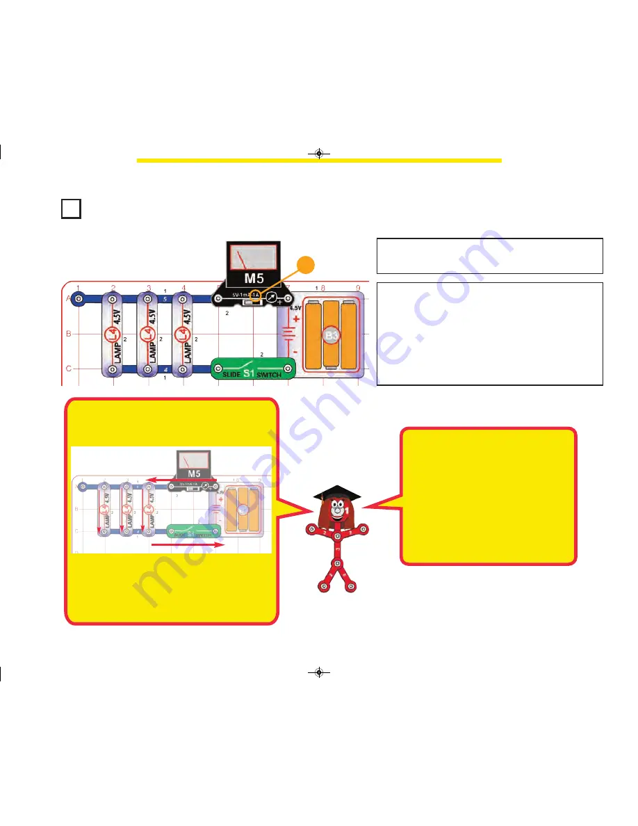
Project 16
Parallel Circuit
Build the circuit, set the meter (M5) to the 1A setting, and turn
on the slide switch (S1). The lamps (L4) are bright and the
meter measures the current.
1A
How would the current change if you removed one or two
lamps? (Try it.)
How would the current change if you replaced one of the
lamps with the white LED (D6)? (Try it.)
In this circuit the batteries produce an electric current,
which flows through the meter, then divides between the
3 lamps, then re-combines and flows through the switch,
and back into the batteries.
The three lamps are connected in parallel with one an-
other. They are bright because each lamp gets the full bat-
tery voltage. The voltage pushes the current with equal
force, because all are 4.5V, down each path.
Most of the lights in your house are connected in parallel;
so if one bulb burns out then the others are not affected.
drawing is saved as Many Paths
Which way does electricity really flow?
In
the above drawing electricity is shown flowing
from the “+” battery terminal, through the cir-
cuit, and back to the “–” battery terminal. This
is how electricity was presumed to flow begin-
ning with discoveries by Benjamin Franklin in
1747. Later discoveries in sub-atomic physics
showed that the charged particles that were
moving (electrons) had a “–” charge, and that
they were moving from “–” to “+” charged ma-
terials.However, understanding circuits is eas-
ier if you assume electricity flows from “+” to
“–”, and all circuit analysis is done this way.
-26-
SC_STEM1_manual_PRINT.qxp_Layout 1 7/13/17 4:42 PM Page 27


