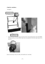
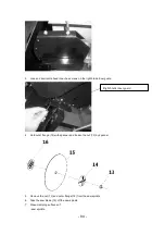
background image


- 78 - 


Procedure 4 


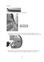
1.  loosen all coach screws , washers, locking nuts on right blade outer guard.   


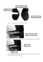
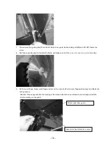
2.  Mount the right blade outer guard on the left blade outer guard with 4coach screw(M6X50) , 4 washer (Ø5),4 

locking nut (M6.) 


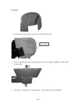
3.  assemble the    protective plate on the working table    with 2 cross groove head screw(M6X8) 


Coach screw   

Содержание 5411074158590

Страница 1: ...I SBE2201 FR SCIE A BUCHES TRADUCTION DES INSTRUCTIONS D ORIGINE NL HOUTBEWERKINGSMACHINE VERTALING VAN DE ORIGINELE INSTRUCTIES GB WOOD WORKING MACHINE ORIGINAL INSTRUCTIONS S28 M07 Y2013...

Страница 2: ...sfaction n utilisez jamais une lame endommag e ou d form e La scie s arr te de fonctionner dans un d lai de 15 minutes apr s avoir coup l alimentation Apr s avoir cess de fonctionner on entend encore...

Страница 3: ...se Le syst me d exploitation de la scie soulage la force de travail Remarque Le diam tre du c ble allong est de 1 5mm 2 si la longueur d passe 20m son diam tre est de 2mm 2 Assurez vous de couper le...

Страница 4: ...fixes pouvant tre retires uniquement a l aide d outils Risques r siduels L apparition du risque de blessures en cas de retrait des dispositifs de protection fixes surement mont s a l aide d un outil l...

Страница 5: ...tion auditive Portez des chaussures de s curit avec pointes en acier Portez des gants de protection Portez un masque respiratoire Utilisation uniquement a l ext rieur N utilisez pas la machine dans un...

Страница 6: ...t es r duisent le risque de d charge lectrique Evitez tout contact corp orel avec des surfaces mises la terre telles que robinets chauffages cuisini res lectriques et r frig rateurs Le risque de d cha...

Страница 7: ...rique dont le commutateur est d fectueux Un outil lectrique ne pouvant plus tre allum ou teint est dangereux et doit tre r par Retirez la fiche secteur de la prise avant de proc der des r glages de re...

Страница 8: ...fier que la machine le c ble d alimentation le c ble de rallonge et la fiche ne sont pas endommages ni uses Le cas ch ant les faire remplacer par un sp cialiste Les d fauts dans la machine y compris l...

Страница 9: ...ge peut tre utilis e Uniquement l ext rieur Seuls les pi ces pouvant tre plac es et maintenues en toute s curit dans la bascule peuvent tre travaill es L utilisation de lames de scie en acier HSS acie...

Страница 10: ...tretien c est adire il n est pas n cessaire de les graisser Les r parations et travaux non d crits dans ce mode d emploi doivent tre effectues uniquement par un personnel qualifie agr e Utiliser uniqu...

Страница 11: ...male ne sont pas non plus inclus dans la garantie AVERTISSEMENT Les mat riaux d emballage ne sont pas des jouets Les enfants ne doivent pas jouer avec des sacs en plastique Il existe un risque de suff...

Страница 12: ...5 m s La valeur totale de vibrations d clar e a t mesur e conform ment une m thode d essai normalis e et peut tre utilis e pour comparer un outil un autre l indication du fait que la valeur totale de...

Страница 13: ...13 SCH MA DES BRANCHEMENTS...

Страница 14: ...glissant 2 table de travail 3 Moteur 4 Protection int rieure de la lame 5 Protection ext rieure de la lame 6 Pied support 7 Cl 2X1 8 Commutateur Marche Arr t 9 support allong 10 Plaque guide 11 bouton...

Страница 15: ...iliser cette machine tant que les parties manquantes ne sont pas remplac es Sous peine d occasionner de graves blessures physiques Ne jetez pas l emballage tant que l inspection n est pas termin e que...

Страница 16: ...12 13 14 15 16 crou de verrouillage crou de verrouillage Vis six pans t te semi circulaire Vis crou Rondelle crou de verrouillage Vis Rondelle Rondelle de ressort M8 M6 M6x12 M5x15 M6 5 M5 M5X12 5 5 4...

Страница 17: ...re la chaleur les liquides agressifs et les bords tranchants Utilisez un c ble enrob de caoutchouc dont la section est suffisante en tant que c ble d extension Ne pas tirer sur le c ble lorsque vous l...

Страница 18: ...e plate et l crou de verrouillage sur le tube de guidage ressort 2 Placez le ressort et la rondelle sur le tube de guidage ressort enfoncez le pied support A vers la lame et ins rez le tube de guidage...

Страница 19: ...on t te bomb e M6X25 la rondelle 6 l crou de verrouillage M6 4 Appuyez de nombreuses fois sur le pied support A pour vous assurer que le pied support A peut revenir dans sa position originale automati...

Страница 20: ...allique attach e au moteur du pied support B et utilisez les 2 boulons M8X15 4 rondelles plates 8 et 2 crous de verrouillage M8 pour les fixer ensemble 3 Montez la protection ext rieure de la lame de...

Страница 21: ...la protection int rieure de la lame de gauche sur le pied support A avec 2 vis six pans t te semi circulaire M6x12 Protection int rieure de la lame de gauche Protection int rieure de la lame de droit...

Страница 22: ...gauche serrez l crou de verrouillage M5 et NE SERREZ PAS la vis 9 Appuyez sur le pied support A vers la lame et assurez vous que cette plaque guide peut fonctionner sans probl mes 10 Placez le rebord...

Страница 23: ...e M5x12 et 2 rondelles pour ressort 5 2 rondelles 5 et ne serrez pas toutes les vis 13 Appuyez sur le pied support A vers la lame et assurez vous que la lame se trouve au centre de la protection int r...

Страница 24: ...ieure de la lame de droite 2 Montez la protection ext rieure de la lame de droite sur la protection ext rieure de la lame de gauche l aide de 4 tire fonds M6X50 4 rondelles 5 4 crous de verrouillage M...

Страница 25: ...upport glissi re sur le pied support A doucement 2 Ensuite serrez le bouton de verrouillage 12 3 Placez le support allong 9 dans le pied support A et faites glisser le support glissi re sur le pied su...

Страница 26: ...iquement revenir dans sa position de d part 4 C ble d alimentation fiche du c ble d alimentation et commutateur s il est endommag faites le remplacer par un lectricien qualifi 5 Frein moteur apr s ext...

Страница 27: ...limentation avec les deux mains sur la poign e 6 Adoptez la bonne position de travail A l avant de la scie Bien en face de la scie D cal par rapport la ligne de coupe 7 Apr s chaque coupe retournez la...

Страница 28: ...vail dans se position de d part Remarque Si la b che n est pas enti rement coup e retournez la et r p tez l op ration de coupe sur le c t oppos coupe inverse 5 Retirez le morceau coup de la bascule d...

Страница 29: ...ction devraient uniquement tre ex cut s par des sp cialistes qualifi s Changer la lame de la scie Danger Directement apr s une coupe la lame de la scie peut tre tr s chaude risque de br lure Si la lam...

Страница 30: ...de droite 4 Maintenez le rebord ext rieur 14 avec la cl et desserrez l crou 13 avec la cl de serrage 5 Retirez l crou 13 et le rebord ext rieur 14 de la broche 6 Retirez la lame de la scie 15 de la b...

Страница 31: ...meules tron onner Panne de la scie Danger Rangez la scie de mani re ce qu elle ne puisse pas tre d marr e par des personnes non autoris es et que personne ne soit bless Attention Ne stockez pas la sc...

Страница 32: ...ent du c ble d alimentation est n cessaire cela doit tre r alis par le fabricant ou son agent pour viter un danger ENTREPOSAGE _ Nettoyez soigneusement toute la machine et ses accessoires _ Entreposez...

Страница 33: ...bespaart u niet alleen elektriciteit maar beschermt u ook de motor Om onbevredigende resultaten te voorkomen mag u nooit beschadigde of misvormde zaagbladen gebruiken De zaag stopt met draaien binnen...

Страница 34: ...wen kunt u de belasting op uw rechterarm verlichten Wanneer u de houtblokbak voorwaarts duwt wordt het blad aangedreven door zijn beveiligingssysteem het springt terug in zijn uitgangspositie het blad...

Страница 35: ...ap de leidende elementen en opvanggoten juist in te stellen Bij werkzaamheden ontstaand stof is vaak gezondheidsschadelijk en mag niet in het lichaam komen Stofafzuiging gebruiken en aanvullend een ge...

Страница 36: ...rd is Hou het apparaat buiten bereik van regen of vocht Het binnendringen van water in een elektrisch apparaat verhoogt het risico op elektrische schokken Beschadig het snoer niet Gebruik de kabel nie...

Страница 37: ...t type van apparaat is voorgeschreven Hou bovendien rekening met de werkomstandigheden en de uit te voeren werkzaamheden Het gebruik van elektrisch gereedschap voor andere doeleinden dan de voorgeschr...

Страница 38: ...randhoutwipzaag mag vanwege een ontbrekende afzuiginrichting uitsluitend buiten gebruikt worden Er mogen enkel werkstukken bewerkt worden die veilig geplaatst en in de wip vastgehouden kunnen worden H...

Страница 39: ...ijke doel worden gebruikt Deactivering van de machine Elke deactivering of verschroting dient door het hiervoor opgeleid personeel uitgevoerd te worden De machine in afzonderlijke onderdelen demontere...

Страница 40: ...gebruikt om een instrument met een ander instrument te vergelijken de aanduiding van het feit dat de aangegeven totale trillingenwaarde ook kan worden gebruikt voor een voorafgaande evaluatie van de...

Страница 41: ...41 AANSLUITSCHEMA...

Страница 42: ...DONDERDELEN 1 Glijdende houder 2 Werktafel 3 Motor 4 Binnenste bladafscherming 5 Buitstens bladafscherming 6 Onderstelpoot 7 Sleutel 8 Aan uit schakelaar 9 Houderverlenging 10 Geleideplaat 11 Grendelk...

Страница 43: ...iet gebruiken alvorens de ontbrekende onderdelen werden gemonteerd Het niet naleven van deze instructie kan leiden tot ernstige lichamelijke letsels Werp het verpakkingsmateriaal niet weg alvorens u d...

Страница 44: ...Moer Borgmoer Onderlegring Schroef M6 M6 6 M5X8 1 2 2 4 3 Procedure 3 4 Procedure 4 1 Slotbout M8X15 2 1 Slotbout M6X50 4 2 Schroef M8X15 1 2 Borgmoer M6 4 3 4 Bout Kruissleufschroef M8X40 M6x15 1 3...

Страница 45: ...pij of een elektricien als u eraan twijfelt of uw huisaansluiting aan deze eisen voldoet Installeer het voedingssnoer zo dat het niet hindert bij het werk en dat het niet beschadigd kan raken Bescherm...

Страница 46: ...slotbout de platte onderlegring en de borgmoer van de veergeleidingsbuis 6 Breng de veer en onderlegring aan op de veergeleidingsbuis druk de steunpoot A naar het blad toe steek de veergeleidingsbuis...

Страница 47: ...unpoot A met slotbout M6X25 onderlegring 6 en borgmoer M6 8 Duw meerdere keren tegen de steunpoot A om na te gaan of de steunpoot A automatisch terugkeert in zijn uitgangspositie 5 Bevestig de twee ha...

Страница 48: ...talen plaat die bevestigd is aan de motor van de steunpoot B en gebruik 2 bouten M8X15 4 platte onderlegringen 8 en 2 borgmoeren M8 om ze aan elkaar te bevestigen 3 Monteer de linker buitenste bladafs...

Страница 49: ...met 2 inbusschroeven met halfronde kop M6x12 6 Op de linker buitenste bladafscherming wordt in de fabriek een geleideplaat 10 gemonteerd Draai de borgmoer M5 op de linker binnenste bladafscherming los...

Страница 50: ...enste flens het blad de buitenste flens en de moer aan op de motoras Houd de buitenste flens vast met een sleutel en draai de moer vast met een sleutel Let op zorg ervoor dat de markering van de draai...

Страница 51: ...rum van de binnenste bladafscherming bevindt en draai het blad met de hand om u ervan te vergewissen dat het blad geen onderdelen kan raken 13 Draai vervolgens alle schroeven vast Procedure 4 4 Verwij...

Страница 52: ...1 aan in de steunpoot A en zorg ervoor dat de glijsteun soepel glijdt op de steunpoot A 6 Draai vervolgens de grendelknop 12 vast 7 Breng de houderverlenging 9 aan in de steunpoot A en zorg ervoor dat...

Страница 53: ...in de poten Alvorens het werk aan te vatten dient u de volgende punten te controleren 1 Zaagblad stevig gemonteerd niet beschadigd geslepen voldoende afstand tot andere onderdelen 2 Bladafscherming on...

Страница 54: ...kt 3 Verwijder kleine afgezaagde stukjes splinters enz nooit met de hand uit de zone vlakbij het draaiende zaagblad 4 Gebruik altijd de werktafel om het te zagen hout naar de zaag toe te bewegen 5 Hou...

Страница 55: ...tie Opmerking Als het houtblok niet volledig is doorgezaagd draait u het om en herhaalt u de zaagbewerking langs de andere kant 5 Verwijder het afgezaagde gedeelte uit de werktafel voer de volgende za...

Страница 56: ...d door gekwalificeerde specialisten Zaagbladverwisseling Gevaar Onmiddellijk na het zagen kan het zaagblad heel heet zijn gevaar voor brandwonden Laat een heet zaagblad eerst afkoelen Reinig het zaagb...

Страница 57: ...onderdelen zouden kunnen doen corroderen dat kan een ongunstig effect hebben op de stabiliteit van de machine Reinig het zaagblad niet met brandbare vloeistoffen 8 Installeer het nieuwe zaagblad 15 re...

Страница 58: ...elijk hebben opgebouwd binnenin de zaagbladafscherming GUARANTEE Voor de garantiebepalingen wordt verwezen naar de bijgevoegde garantievoorwaarden MILIEU Als uw machine na verloop van tijd aan vervang...

Страница 59: ...o make sure that the cable is not damaged scratches or cracks c Ensure that there is no dirt or other things that could jump start the machine d Remove any objects near the machine may be affected by...

Страница 60: ...t or wrapped with fi xed safely attached safety equipment removable with a tool only Residual risk Risk of electric shock if the fi xed safely attached cover removed from a running and plugged machine...

Страница 61: ...gerators There is an increased risk of an electric shock if your body is earthed Do not expose power tools to rain or wet conditions If water gets inside a power tool it will increase the risk of an e...

Страница 62: ...face and the fl oor around the machine must be fl at well maintained and with no waste such as sawdust and cuttings The processed bundle of workpieces and fi nished workpieces should be placed near th...

Страница 63: ...or by customer services specifi ed by us The machine must not be used in an explosionrisk environment and must not be exposed to rain Metal parts nails etc must necessarily be removed from the materi...

Страница 64: ...and delivered to a rubber parts collection centre There is no other residual risk after deactivation and blocking of the moving parts Electrical structural elements are a special waste and need to be...

Страница 65: ...d vibration total value has been measured in accordance with a standard test method and may be used for comparing one tool with another that the declared vibration total value may also be used in a pr...

Страница 66: ...66 WIRING DIAGRAM...

Страница 67: ...ST OF MAIN PART 1 Sliding support 2 working table 3 Motor 4 Blade inner guard 5 Blade outer guard 6 Support leg 7 Spanner 2X1 8 On Off switch 9 extended holder 10 Guide plate 11 locking knob 12 lockin...

Страница 68: ...he list of loose parts If any parts are missing do not operate this machine until the missing parts are replaced Failure to do so could result in serious personal injury Do not discard the packing mat...

Страница 69: ...s and etc contains No Description Specificati ons Q ty No Description Specifications Q ty 1 Procedure 1 2 Procedure 2 1 Screw M4X55 4 1 Screw M6X25 2 2 3 4 5 Bolt Flat washer Locking nut Washer M8X60...

Страница 70: ...nstalled earthed and tested Mains voltage and frequency must conform with the date stated on the machine s nameplate Fuse protection by a residual current device RCD of 30 mA fault current sensitivity...

Страница 71: ...the two holes on the supporting leg B and use 2 bolts M8X60 4 flat washers 8 and 2 locking nut M8 to fasten these two legs together and leave the supporting leg to lie on the ground 2 Mount the switch...

Страница 72: ...72 Procedure 2 1 loosen coach bolt flat washer and locking nut on spring guide tube...

Страница 73: ...h coach bolt M6x25 with nut flat washers 6 locking nut M6 3 fasten the chain on supporting leg B on the supporting leg A with coach bolt M6X25 washer 6 locking nut M6 4 push the supporting leg A many...

Страница 74: ...he metal plate attached to the motor of the supporting leg B and use 2 bolts M8X15 4 flat washers 8 and 2 locking nut M8 to fasten these together 3 Mount the left blade outer guard on the supporting l...

Страница 75: ...2 semicircle head inner hex screws M6x12 6 There is a guide plate 10 assembled on the left blade outer guard before shipping out from the manufacturer Loosen locking nut M5 on left blade inner guard...

Страница 76: ...re that this guide plate can be operated smoothly 9 Put the inner flange blade outer flange and nut on the motor shaft Hold outer flange with spanner and fasten the nut by spanner Attention Please pay...

Страница 77: ...ard with 2 semicircle groove head screw M5x12 and 2 spring washer 5 2 washer 5 and do not fasten all the screws 12 Push the supporting leg A towards the blade and make sure that the blade is in the ce...

Страница 78: ...ing nuts on right blade outer guard 2 Mount the right blade outer guard on the left blade outer guard with 4coach screw M6X50 4 washer 5 4 locking nut M6 3 assemble the protective plate on the working...

Страница 79: ...ing support to slide on the supporting leg A smoothly 2 Then to fasten the locking knob 12 3 Put the extended holder 9 into the supporting leg A and make the sliding support to slide on the supporting...

Страница 80: ...the Bottom of the Stand Before starting work check to see that the following are in proper working order 1 Saw blade firmly mounted Undamaged Sharp Sufficient distance to other parts 2 Blade guard und...

Страница 81: ...crushing by moving parts 1 Do not operate the machine without installed guards 2 Keep sufficient distance to driven components when operating the electric tool 3 De not remove small cutoffs splinters...

Страница 82: ...sure that the motor speed does not fall off Push feed working table until it hits the stop 4 Return working table completely to the starting position Note If the log was not completely separated turn...

Страница 83: ...han described in this section should only be carried out by qualified specialists 4 Saw blade change Danger Directly after cutting the saw blade can be very hot burning hazard Let a hot saw blade cool...

Страница 84: ...t blade inner guard 4 Hold outer flange 14 with spanner and loosen the nut 13 by spanner 5 Remove the nut 13 and outer flange 14 from the saw spindle 6 Take the saw blade 15 off the saw spindle 7 Clea...

Страница 85: ...ecifications and EN 847 1 parts of unsuitable or damaged saw blades may be hurled away explosive like Do not use saw blades made of high speed steel HS or HSS saw blades with visible damage cut off wh...

Страница 86: ...t put it in the domestic waste but dispose of it in an environmentally safe way SERVICE DEPARTMENT _ Damaged switches must be replaced by our after sales service department _ If replacing the power co...

Страница 87: ...87...

Страница 88: ...55014 1 A2 2011 EN 55014 2 A2 2008 EN 61000 3 2 A2 2009 EN 61000 3 11 2000 Caract ristiques techniques Produit SCIE A BUCHE Type SBE2201 Tension du r seau V 230 Fr quence du r seau Hz 50 Puissance W...

Страница 89: ...1870 6 A1 2009 EN 60204 1 A1 2009 EN 55014 1 A2 2011 EN 55014 2 A2 2008 EN 61000 3 2 A2 2009 EN 61000 3 11 2000 Technische Daten Product HOUTBEWERKINGSMACHINE Type SBE2201 Netspanning V 230 Netfrequen...

Страница 90: ...2009 EN 55014 1 A2 2011 EN 55014 2 A2 2008 EN 61000 3 2 A2 2009 EN 61000 3 11 2000 Technical Data Product WOOD WORKING MACHINE Type SBE2201 Mains voltage V 230 Mains frequency Hz 50 Power input W 220...

Страница 91: ...ierte Normen EN 1870 6 A1 2009 EN 60204 1 A1 2009 EN 55014 1 A2 2011 EN 55014 2 A2 2008 EN 61000 3 2 A2 2009 EN 61000 3 11 2000 Technische Daten Produkt HOLZ GE Typ SBE2201 Netzspannung V 230 Netzfreq...

Страница 92: ...de Goz e 6110 Montigny le Tilleul Belgique T l 0032 71 29 70 70 Fax 0032 71 29 70 86 Made in China S A V sav eco repa com Service Parts separated 32 71 29 70 83 32 71 29 70 86 Fabriqu en Chine 2013 Ma...

Отзывы: