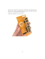
The short pins should be pointing through to the top-side of the PCB, while
the plastic and longer side of the pins should be visible on the back of the
PCB. Make sure the plastic lock tab is facing down.
The side of the PCB with the text “5U POWER” is the bottom side of the
PCB.
The holes for the power header are offset slightly in both positions so that
once inserted, the power header will stay in position while you solder it.
7
Содержание 3340 VCO
Страница 1: ...Electrosmith 3340 VCO MU Build Guide 1 ...
Страница 4: ...Build 4 ...
Страница 5: ...Build 5 ...
Страница 6: ...1 Power Header 6 ...
Страница 8: ...8 ...
Страница 9: ...Once soldered clip the pin labeled K from the power header 9 ...
Страница 10: ...2 Link Headers 10 ...
Страница 12: ...12 ...
Страница 14: ...14 ...
Страница 15: ...3 Submodule 15 ...
Страница 16: ...Connect the female and male headers together 16 ...
Страница 17: ...With the board face down insert the female headers into the 1MU PCB 17 ...
Страница 20: ...20 ...
Страница 21: ...4 Jacks and Pots 21 ...
Страница 24: ...Install the front panel so that all of the jacks and pots fit into their holes 24 ...
Страница 28: ...28 ...
Страница 29: ...Attach the link cable aligning the red stripe to the white indicator on both pcb s You re done Enjoy 29 ...


