Test
Double check that Pin 1 (GND) of the Submodule, indicated by a square
copper pad, matches the pin 1 indicator on the 1 MU PCB.
Attach the power cable to the Electrosmith 3340 VCO.
Power on the module.
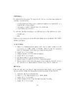
A tone should emit from the top four jacks (Sine, Triangle, Ramp, Square)
Adjusting the top two pots (Coarse, and Fine) should change the frequency
of the tone.
The Bottom knob (PWM) should change the sound of the square wave by
adjusting the pulse width.
Plugging another oscillator (ramp or square wave) into Sync should change
the sound by resetting the phase on the edges of the incoming signal.
Adjusting the Soft/Hard toggle should change the way Sync sounds.
Plugging a moving signal into LFM and adjusting the LIN FM knob should
change the frequency of the tone.
Plugging a moving signal into EFM and adjusting the EXP FM knob should
change the frequency of the tone.
Plugging a signal into VOCT should change the frequency of the tone.
30
Содержание 3340 VCO
Страница 1: ...Electrosmith 3340 VCO MU Build Guide 1 ...
Страница 4: ...Build 4 ...
Страница 5: ...Build 5 ...
Страница 6: ...1 Power Header 6 ...
Страница 8: ...8 ...
Страница 9: ...Once soldered clip the pin labeled K from the power header 9 ...
Страница 10: ...2 Link Headers 10 ...
Страница 12: ...12 ...
Страница 14: ...14 ...
Страница 15: ...3 Submodule 15 ...
Страница 16: ...Connect the female and male headers together 16 ...
Страница 17: ...With the board face down insert the female headers into the 1MU PCB 17 ...
Страница 20: ...20 ...
Страница 21: ...4 Jacks and Pots 21 ...
Страница 24: ...Install the front panel so that all of the jacks and pots fit into their holes 24 ...
Страница 28: ...28 ...
Страница 29: ...Attach the link cable aligning the red stripe to the white indicator on both pcb s You re done Enjoy 29 ...


