


14
To perform the firmware update from a batch file. Create a batch file contains the following
line:
(NOTE: The Following is a single line)
C:\Users\Carlo\AppData\Local\Arduino15\packages\esp32\tools\esptool\2.3.1/esptool.exe --chip
esp32 --port COM5 --baud 921600 --before default_reset --after hard_reset write_flash -z --
flash_mode dio --flash_freq 80m --flash_size detect 0xe000
D:\Applications\Data\KiCAD\KiCadProjects\GuruModem\firmware\boot_app0.bin 0x1000
D:\Applications\Data\KiCAD\KiCadProjects\GuruModem\firmware\bootloader_qio_80m.bin 0x10000
D:\Applications\Data\KiCAD\KiCadProjects\GuruModem\firmware\zimodem.ino.bin 0x8000
D:\Applications\Data\KiCAD\KiCadProjects\GuruModem\firmware\zimodem.ino.partitions.bin
The paths will need to be changed on your system based on where your Arduino
environment, and your firmware files are stored.
Three files are supplied with the Arduino IDE.
esptool.exe boot_app0.bin
bootloader_qio_80m.bin
Two files will be generated from your build of the firmware.
zimodem.ino.bin
zimodem.ino.partitions.bin
The FTDI model TTL-232R-3.3V cable is required.
Configuring the hardware for firmware downloading
The GuruModem card must be connected to the computer over an FTDI cable attached to
P1. +5 V must be applied to the GuruModem before programming.
Attaching the FTDI
cable to the card incorrectly may result in damage.
1.
Build or acquire the firmware file you wish to download to the GuruModem card.
2.
Attach the FTDI cable to P1 on the GuruModem card.
3.
Connect the +5 V power to the micro USB connector J2.
4.
Press and hold the PROG button (SW1).
5.
Press and hold the RESET button(SW2).
6.
Release the RESET button.
7.
Release the PROG button.
8.
Start the firmware download.
9.
When the download is complete press the RESET button.
10.
Disconnect the FTDI cable and power.
Содержание GURUMODEM
Страница 3: ...INDEX 30 ...
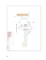
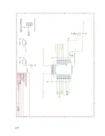
Страница 27: ...24 SCHEMATICS ...
Страница 28: ...25 ...
Страница 29: ...26 ...
Страница 30: ...27 ...
Страница 31: ...28 ...
Страница 32: ...29 BOARD LAYOUT ...