background image

ENGLISH

2. 

BEFORE INSTALLATION

2.1 

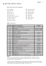
Tools needs for installation

1. 

Level gauge

2. 

Screw driver

3. 

Electric drill

4. 

Hole core drill

5. 

Flaring tool set

6. 

Specied torque wrenches

7. 

Spanner (half union)

8. 

A glass of water

9. 

Hexagonal wrench

10. 

Gas-leak detector

11. 

Vacuum pump

12. 

Gauge manifold

13. 

Pipe expander

14. 

Multimeter

15. 

Pipe cutter

16. 

Measuring tape

17. 

Other tools

2.2 

Accessories

Number

Name of Accessories

Quantity

1

Indoor unit mounting plate

1

2

Clip anchor

Varies by models

3

Self-tapping screws (for mounting plate)

Varies by models

4

Remote controller

1

5

Remote controller Holder / Screws

Optional

6

Battery (AAA 1.5V)

2

7

Piping hole cover

Optional

8

Pipe insulation belt

1

9

Refrigerant piping (Liquid/Gas pipe)

Optional

10

Signal cable

Optional

11

Drain hose

1

12

Cushion

Optional

13

Drain connector (Heat Pump model only)

Optional

14

Drain plug (Heat Pump model only)

Optional

15

Flare nut (for gas pipe)

Optional

16

Flare nut (for liquid pipe)

Optional

17

Handle screw (for outdoor unit)

Optional

18

Wall mud

Optional

19

Magnetic ring

Optional

20

Healthy filter**

 (Packed in the plastic bag)

Varies by models

Note:


The accessory parts may vary from each model, please refer to the actual parts. 

Other necessary parts for the installation, besides the above mentioned, must be 

provided by the customer/installer.


**


Please install the Healthy filter like Active carbon filter, Bio-Hepa filter, Vitamin C filter, 

Silver ion filter or any other filters with the dust filter in the indoor unit. For some models, 

we already have the Healthy filters installed in the indoor unit.

Содержание ESM09CRR-B3

Страница 1: ...EN AIR CONDITIONER INSTALLATION MANUAL 2 ESM09CRR B3 ESM12CRR B3 ESM18CRR B3 ESV09CRS B2 ESV12CRS B2 ESV09CRR C6 ESV09CRR C7 ...

Страница 2: ...ister your product for better service www electrolux com productregistration Buy Accessories Consumables and Original spare parts for your appliance www electrolux com shop CUSTOMER CARE AND SERVICE We recommend the use of original spare parts When contacting Service ensure that you have the following data available The information can be found on the rating plate Model PNC Serial Number Warning C...

Страница 3: ...ccordance with the national wiring standards and the electricity suppliers service rules by authorised personnel only If the unit is to be moved to another location or disposed of only a suitably qualified person is permitted to undertake such work If you notice an unusal situation such as a burning smell please switch off the power to the air conditioner and contact the brand service agent If thi...

Страница 4: ...Do not block the air inlet or outlet It will result in insufficient performance and cause malfunctions Keep combustible materials away from the units at least 1meter It may cause fire Do not step on the top of the outdoor unit or place heavy things on it It may cause damage or injury Do not attempt to repair the air conditioner by yourself Incorrect repairs may cause electric shock or fire Please con...

Страница 5: ...t 1 9 Refrigerant piping Liquid Gas pipe Optional 10 Signal cable Optional 11 Drain hose 1 12 Cushion Optional 13 Drain connector Heat Pump model only Optional 14 Drain plug Heat Pump model only Optional 15 Flare nut for gas pipe Optional 16 Flare nut for liquid pipe Optional 17 Handle screw for outdoor unit Optional 18 Wall mud Optional 19 Magnetic ring Optional 20 Healthy filter Packed in the pl...

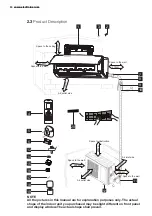
Страница 6: ...or unit you purchased may be slight different on front panel and display window The actual shape shall prevail 15cm 15cm Space to the wall Space to obstruction 30cm 2m Air outlet side Air inlet side 50cm Space to the wall Space to the ceiling 15cm Space to the wall 3 m Air outlet side Space to the wall 50cm 1 2 3 4 20 5 6 13 14 15 16 11 7 10 9 8 17 18 19 12 3 0 c m ...

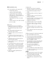
Страница 7: ...llation distances specified in this document Do not block the air inlet or the air outlet Install the outdoor unit out of reach of children Install the outdoor unit where there is sufficient ventilation Install the outdoor unit where produced noise and airflow will not disturb neighbors or animals Install the outdoor unit in a dry place Install the outdoor unit in a place not exposed to direct sunli...

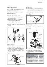
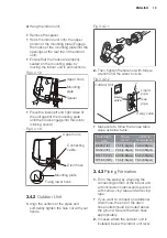
Страница 8: ...ng plate and drill the pipe hole so that it is tilted slightly downward 2 Always use a pipe cover with an opening when drilling Fig 3 1 2 5 7mm Wall Indoor Outdoor 3 1 3 Connective pipe 1 For the left hand and right hand piping remove the pipe cover from the side panel The pipe cover can be kept as it may be used when relocating the air conditioner to any other place 2 For the rear right hand and ...

Страница 9: ...urely and evenly as shown in the Fig 3 1 6 2 Because the condensed water from rear of the indoor unit is gathered in ponding box and is piped out of room do not put anything else in the box Fig 3 1 6 NOTE Connect the indoor unit first then the outdoor unit Be careful not to let the drain hose slack Both of the auxiliary piping should be heat insulated Be sure that the drain hose is located at the ...

Страница 10: ...t pump model 1 During heating operation the condensate and defrosting water should be drained out reliably through the drain hose 2 Install the outdoor drain connector in the drain water hole on the chassis of outdoor unit and attach the drain hose to the connector so that the waste water formed in the outdoor unit can be drained out 3 The drain water hole must be plugged Whether to plug other hol...

Страница 11: ...nd of the copper tube pipe in a downward direction as you remove burrs in order to avoid dropping burrs into the tubing Fig 3 3 1 2 3 Put nut on Remove flare nuts attached to indoor and outdoor unit then put them on pipe tube after completed burr removal It is not possible to put them on after flaring work Fig 3 3 1 3 4 Flaring work Carry out flaring work using flaring tool as shown below Fig 3 3 ...

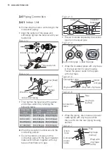
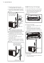
Страница 12: ...ulation material Bind them together with vinyl tape so that there is no gap Fig 3 4 1 3 Ensure to isolate separately the suction pipe from the liquid pipe Fig 3 4 1 4 Wrap the insulated pipes with vinyl tape in the rear section for pipe housing Fasten the power cable to the pipes with vinyl tape Fig 3 4 1 5 Fig 3 4 1 6 Wrap the piping drain hose and power cable tightly with vinyl tape so that they...

Страница 13: ... the wrench clicks Fig 3 4 2 2 2 way valve Make sure to follow the torque table value as below table Outer diam mm Torque N m Additional Torque N m Ф6 35 1 4 15 7 1 6kg m 19 6 2 0kg m Ф9 52 3 8 29 4 3 0kg m 34 3 3 5kg m Ф12 70 1 2 49 0 5 0kg m 53 9 5 5kg m Ф15 88 5 8 73 6 7 5kg m 78 6 8 0kg m 3 4 3 Piping Formation 1 Form the piping by wrapping the connecting portion of the indoor unit with insula...

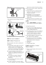
Страница 14: ...lift the indoor unit front panel Hold the lower part of the left and right sides of the panel pull it against you and lift it stops with support Fig 3 4 4 1 2 Check the drainage Carefully pour a glass of water on the evaporator Ensure the water flows through the drain hose of the indoor unit without any leakage and goes out the drain exit Fig 3 4 4 2 3 Dain piping The drain hose should point downw...

Страница 15: ... socket are properly connected 8 Inadequate or incorrect electrical connections may cause electric shock fire or some electrical parts to malfunction 9 Before performing any electrical work turn off the main power to the system NOTE Refer to Appendix 2 for correlative specs about the Electrical Installation Earthing Requirements 1 The unit must be reliably earthed and connected to the special eart...

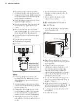
Страница 16: ...r new power cord Lengthen the power cord by yourself is not allowed After tightening the screws pull the wire slightly to confirm whether it s firm or not Do not connect two power cables together to supply power to the air conditioner Do not extend the power cable conductor by cutting 3 5 3 Installation of Outdoor Electric Wires 1 Remove the handle on the right side plate of outdoor unit Fig 3 5 3...

Страница 17: ...eating only for models with heating function efficiency drops Moisture in the refrigerant circuit may freeze and block capillary tubing Water may lead to corrosion of parts in the refrigeration system Therefore the indoor unit and tubing between the indoor and outdoor unit must apply leakage test and be evacuated to remove any noncondensables and moisture from the system 3 6 1 Air Purging With Vac...

Страница 18: ...efrigerant Indoor Unit Outdoor Unit Lo stop valve 3 way valve Gas side Liquid side Hi stop valve 2 way valve Half union NOTE There is a charging port integrated in the low side outlet but not in the high side outlet The low side outlet is shown in the sketch map below Fig 3 6 2 2 Flare nut Valve body Charge port Valve stem Cap Stopper 3 6 3 When using the vacuum pump For method of using a manifold...

Страница 19: ...t then tighten the flare nut again Make sure the pressure display in the pressure indicator is a little higher than the atmospheric pressure This procedure verifies if the refrigerant goes through the tubes correctly 7 Close the schrader valve then remove the valve core tool Replace the charging port cap 8 Fully open the packed valve stems B and A 9 Securely tighten the cap of the packed valve Fig...

Страница 20: ...he remote is unavailable or in case of maintenance 4 4 Pump Down When relocating or disposing of the air conditioner pump down the system following the procedure as below so that no refrigerant is released into the atmosphere Connect the hose of manifold valve to the charge port of stop valve on the gas pipe side of the outdoor unit Close the stop valve on the gas pipe side almost completely Fully...

Страница 21: ...0 545 315 A A B Outdoor Unit Dimension mm 750 285 200 665 420 280 A 750 285 200 730 545 285 A 750 285 200 837 296 205 A A 730 545 285 837 296 205 952 310 227 825 655 310 B 952 310 227 900 700 350 C 1082 330 233 Indoor Unit Dimension mm Mounting Plate Type 800 545 315 750 285 200 Type A Type B Type C ...

Страница 22: ...nal Area of Power and Power Cables Cable Types Indoor power cable H05VV F if applicable Power cable H07RN F or H05RN F The size of the power supply cable signal cable fuse and switch needed is determined by the maximum current of the unit The maximum current is indicated on the nameplate located on the side panel of the unit Refer to this nameplate to choose the right cable fuse or switch ...

Страница 23: ...alled connecting pipe length m R Additional refrigerant required per meter of connecting pipe g m refer to the above table Example If the totel length A for 9K model is 10m then the additional refrigerant need to fill by M M 10 7 5 x 12 30g Models Gas Pipe Diameter mm Standard Length m Maximum Length m A Maximum Height m B Additional Refrigerant g m Liquid Pipe Diameter mm 5 12 15 10 Ø9 52 3 8 Ø6 ...

Страница 24: ...www electrolux com shop 91030a ...

Отзывы: