Euro-500TX Handy
© Elcom, s. r. o.
Service manual
28
Euro-500TX Handy
© Elcom, s. r. o.
Service manual
29
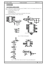
3.2.2 Data processing in the printing head
The printing head has four gates (strobes) that allow the printing to be divided into four parts. The corres-
pondence of these gates to individual thermal elements is shown in following table. Actual printing is divided
into two parts (two gate signals are activated simultaneously).
3.2.3 Printing data and their position
The 576 bits of data that are carried by the DATA IN signal are printer in positions as shown in the picture
below. The data lying in the gap between the receipt and the journal are permanently equal to zero.
3.2.4 Thermistor specification
a)
electrical characteristics
resistance 30 kΩ ± 5 % at 25 °C
B constant
3,950 K ± 2 %
b)
ranges temperature range:
-20 to +80 °C
c)
relation between temperature and resistance:
R
X
:
resistance at chosen temperature (°C)
R
25
:
resistance at 25 °C (30 kΩ ± 5 %)
B:
3,950 K ± 2 % (constant)
EXP (x): natural logarithm
3.2.5 Time diagram
STB #
Thermal element #
Dots per STB
1
1 - 144
64
2
145 - 288
64
3
289 - 432
64
4
433 - 576
64
Tab. 3.1 Gates (strobes) placement
PRINTER MECHANISM
MOTOR
Gap between the receipt and journal
DATA IN
1 2 3 4 ......................................................576
Printing side
Tape feed direction
Fig. 3.2 Printing data placement
tw LAT
tsetup STB
tdo
tdo
tw setup LAT tw hold LAT
tsetup DI
thold DI
tw CLK
DRIVER OUT
STROBE (STB)
LATCH (LAT)
High: HOLD
Low: THROUGH
DATA IN (DI)
CLOCK (CLK)
DATA OUT (DO)
td DO
Fig. 3.3 Time diagram


