elco MHS Boilers Trispace AR 135 Скачать руководство пользователя страница 15

Trispace AR Floor Standing Shell and TubeBoiler 


15                                                                           L360                                            

©

MHS Boilers 06/09/2013 


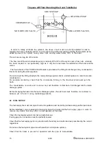
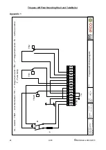
In  order  to  totally  eliminate  the  problem,  the  above  circuit  must  be correctly adjusted in order to 

maintain the boiler constantly at 55°C even at night and a further temperature-limiting thermostat must be 
added to prevent  the  system  mixing  valve  from  sending  water  below  55°C  to  the boiler.  
 
This will ensure long life of the boiler.  
  
 The flow rate of the anti-condensate pump is normally 25%-30% of the system pump  flow  rate,  whereas  
the  head  required  is  not  particularly  high  as  it  only has to overcome the resistance of the boiler and the 
valves. 
 
  The flue collector of the TRISPACE AR boilers is provided with a fitting for discharge of any condensation 
that forms during the start-up phase.  
  
Do not connect the fitting directly to the mains drainage system but to a collecting basin in order to monitor 
condensation.  
For  accurate  monitoring,  check  that  the  condensate  forming  in  the  flue does not also end up in the 
basin.  
  
The  condensation  is  acidic  and  corrosive  and  will  therefore  contaminate  if discharged into the mains 
drainage system.   
  
Before emptying the basin into the mains drainage system, the acid level must  therefore  be  restored  to  
between  pH  6.5  and  9  using  neutralising products.  


22  FUEL SUPPLY  


The fuel supply line must comply with current regulations and be laid by professionally qualified personnel.  
  
Before installation, you are advised to thoroughly clean the inside of all the fuel  supply  pipes  in  order  to  
remove  any  debris  that  may  affect  correct operation of the boiler.  
  
Check the fuel supply system internal and external seal.   
If using gas, the connections must be perfectly sealed.  
  
Check that the fuel supply system is provided with the safety and control devices prescribed by the current 
regulations.  
  
Do not use the fuel system pipes to earth electrical or telephone systems.  


Check  that  the  boiler  is  pre-set  for  operation  with  the  type  of  fuel available.  
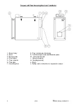
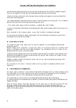
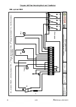
 

HEATING PUMP 

SHUNT PUMP 

THERMOSTAT 

ISOLATION VALVES 

NON RETURN VALVE 

Содержание MHS Boilers Trispace AR 135

Страница 1: ...space AR Floor Standing Shell and Tube Boiler Operating Maintenance Manual MHS Boilers Ltd 3 Juniper West Fenton Way Basildon Essex SS15 6SJ Telephone 01268 546700 Fax 01268888270 WWW MHSBOILERS COM L...

Страница 2: ...INTENANCE 11 15 PRODUCT RECEIPT 11 16 INSTALLATION 13 17 INSTALLATION PREMISES 13 18 DISCHARGE OF COMBUSTION PRODUCTS 13 19 HYDRAULIC CONNECTION 13 20 ELECTRICAL SYSTEM 14 21 THE PROBLEM OF CONDENSATE...

Страница 3: ...ersonnel The term professionally qualified personnel means persons with specific technical skills in the sector of heating systems and components for domestic use and domestic hot water production To...

Страница 4: ...essionally qualified personnel The Trispace AR boiler is CE approved and applies to the following European standards 92 42 EEC Boiler efficiency directive 90 396 EEC Gas appliance directive 73 23 EEC...

Страница 5: ...593 2006 Code of Practice for treatment of water in domestic hot water central heating systems BS 7671 2008 Requirements for electrical installations IEE Wiring Regulations Seventeenth Edition BS EN 1...

Страница 6: ...o the boilers General description Technical specifications Requirements for design and installation Maintenance instructions The operating instructions for the user have been affixed to the appliance...

Страница 7: ...eat absorption is therefore obtained without noxious gas or thermal stresses and above all with over 93 increase in the working efficiency On leaving the dry pipes the products of combustion are colle...

Страница 8: ...1 Boiler body 8 Flue condensate discharge 2 Door 9 Technical specs and identification plate 3 Burner plate 10 Instrument board 4 Pilot flame r Return heating 5 Flue collector m Heating delivery 6 Flu...

Страница 9: ...1225 1890 2120 Maximum working pressure bar 5 6 Minimum return working temperature C 50 Maximum allowable temperature C 100 9 IDENTIFICATION ELEMENTS The appliance can be identified through the Data...

Страница 10: ...hermostat is active and set to 20 C that the system pumps are not blocked Turn on the master switch and then the main switch on the control panel The boiler will perform an ignition phase and once sta...

Страница 11: ...ic maintenance and measurement of the combustion efficiency are required and the person in charge of the heating system must ensure that these checks are carried out by professionally qualified person...

Страница 12: ...720 720 720 820 820 820 950 1000 mm L1 758 860 1010 1260 1260 1260 1510 1510 1612 1612 1812 2016 2266 mm L2 405 470 520 520 520 560 560 560 660 660 660 640 640 mm L3 388 330 440 690 690 690 940 940 9...

Страница 13: ...of rigid hermetically sealed pipes resistant to high temperatures condensation and mechanical stress For sealing the joints use materials that can withstand at least 250 C Badly sized and shaped flues...

Страница 14: ...e with the current safety regulations The manufacturer will not be liable for any damage caused by failure to earth the system Call professionally qualified personnel to check that the electrical syst...

Страница 15: ...nitoring check that the condensate forming in the flue does not also end up in the basin The condensation is acidic and corrosive and will therefore contaminate if discharged into the mains drainage s...

Страница 16: ...damaging the boiler IMPORTANT after installing the burner fill any space between the draught tube and the hole of the door with the material provided resistant to 1000 C ceramic fibre mat This operati...

Страница 17: ...p of the panel on the corner elements of the boiler structure Fit the right side panel s 2 taking the same precautions as with the left side To fit the rear casing proceed as follows position the bott...

Страница 18: ...owing the electric wiring diagram Appendix 1 page 28 Do not fix the electrical cables on the boiler body sheet metal panels on the door or on the flue collector Close the control board 26 PRELIMINARY...

Страница 19: ...ets on the water and combustion side they must be further tightened while hot in order to guarantee a perfect seal This operation is of fundamental importance for the gaskets of the door of the burner...

Страница 20: ...opening is normally from left to right To open the door remove the fixing nuts from the left Lifting equipment must be used to change the door opening direction Proceed as follows hook the door to th...

Страница 21: ...that the combustion circuit is perfectly sealed and replace any worn gaskets Check the system hydraulic seal to avoid unnecessary exchange of water and topping up which will increase the risk of scali...

Страница 22: ...ets easily covered with soot REMEDY check the burner regulation combustion check the fuel quality check the flue for clogging and the cleanness of the burner air intake dust FAULT smell of gas and or...

Страница 23: ...eck the efficiency of the expansion vessel check the calibration of the valve itself FAULT overheating due to lack of water in the boiler REMEDY Turn off the burner do not pour water and do not open t...

Страница 24: ...ness Park Basildon Essex SS15 6SJ Tel 01268 546700 Drawn by Date Title Version Drg Nr Pages Jim Wyborn 10 th September 2013 1 1 MHS 1 01 2 Trispace AR Wiring diagram 1 2 3 4 5 6 7 8 9 10 11 12 13 S3 B...

Страница 25: ...Date Title Version Drg Nr Pages Jim Wyborn 10 th September 2013 1 1 MHS 1 01 2 Trispace AR Wiring diagram with optional BMS relays 1 2 3 4 5 6 7 8 9 10 11 12 13 S3 B4 T T T L F IG TSAH TR1 TR2 TA IG...

Страница 26: ...Trispace AR Floor Standing Shell and TubeBoiler 26 L360 MHS Boilers 06 09 2013 34 NOTES...

Отзывы: