background image

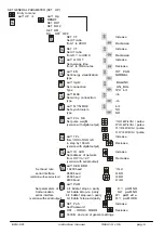
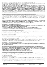
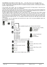
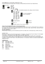
PROGRAMMING OF THE HOURS COUNTER (SET   HR_) 
The hour counter will be increased when the measure of the parameter will exceed the set threshold value. 


ELM-961 


instruction manual

IM441-U v0.6 

pag. 11


seT  UP  

Æ  

seT  Up 

RESET 
SET   DO1 
SET   DO2 
SET   HR_ 
--- OFF   OFF  

(the visualization depends on the settings and the I/O status) 


HR_ SEl  VLN 
HR_ SEl  AMP 
HR_ SEl  P.f  To 

chose 

the 

parameter 

HR_ SEl  ACT  

(see the variable list) 

HR_ SEl  REA 
HR_ SEl  APP 
HR_ SEl  VLL 
HR_  SEL  FRE 
HR_  sel T°c 


Set the threshold  

Increase 

HR_  HI  

Decrease 

Confirm  and end of hour  counter  settings. 

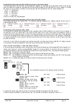
SELECT THE PARAMETER TO LINK TO THE HOURS COUNTER 
From the previous setting, pressing the C key it’s possible to set the hours counter: the message SET   HR_ appears on 
the F display. Press the A key to define the parameter to link to the hours counter. Press more time the B key to select 
the parameter and the A key to confirm it. 
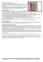
SET THE THRESHOLD 
Subsequently it’s necessary to set the threshold using the B (to increase) and C (to decrease) keys. Confirm with A key. 


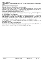
I/O INFO PAGE 
After the hour counter set, the I/O info page appears in F displays: on the second part (L2) the status of the first digital 
output (DO1), on the third part (L3) the status of the second digital output (DO2). 
The visualization of the status of the two digital outputs is ON  if the digital output is activated or OFF  if deactivated. 
The status of the serial port appear on the G display when the instrument has this option. If the instrument receives data, 
it displays the letter R and the number of the instrument that is in communication while if the instrument transmits data, it 
displays the letter T. 


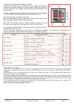
VARIABLE  LIST 
VLN      three-phase voltage 
AMP        three-phase current 
P.F          three-phase power factor 
ACT  

active power 

REA  

reactive power 

APP  apparent 

power 

VLL       phase to phase voltage 
FRE        frequency 
T°C         temperature 

Содержание ELM-961

Страница 1: ...internal CT digital output in alternative to the serial port serial port in alternative to the digital output power supply different from standard version current input 1A MEASURED PARAMETERS paramete...

Страница 2: ...400V 300 500V phase to phase 175 290V phase neutral 230V 175 290V phase to phase 130 170V phase neutral L2 L3 phase to phase power supply 110V 85 145V phase to phase 50 85V phase neutral 230V 300 500V...

Страница 3: ...IRES ELM on line with 3 wires without neutral or with neutral not supplied the N terminal must not be connected L1 S1 P1 S1 L2 P1 L3 N S1 S2 P1 P2 LOAD I1 I3 VL1 VL2 VL3 INSERTION ON THREE PHASE LINE...

Страница 4: ...N ON SINGLE PHASE LINE I1 I2 S1 I3 VL1 VL2 VL3 if the multimeters are used on single phase line the measure are referred at the L3 phase The others data displayed relatives at value of three phase sys...

Страница 5: ...the values of the active reactive and apparent energy counters If it s selected with the A and B keys the display indicates the maximum and average values G display for the visualization of the electr...

Страница 6: ...kVAr pulse version with digital output 01 0 kW kVAr pulse 0 10 kW kVAr pulse 0 01 kW kVAr pulse seT TPL Increase from 100 to 500 mS in step by 100 mS Decrease version with digital output seT ID ADR In...

Страница 7: ...decrease it press the C key To confirm it press the A key The average time is the time used to calculate the average parameters avg and the maximum demand maxD Programming of the energy visualization...

Страница 8: ...rd when required by the instrument at the enter of the setup use the A B and C keys as the same way done previously The menu is cyclic After the last setting the instrument go back to the first page o...

Страница 9: ...ALR LO With ALR SYS 123 the digital output will function as alarm verifying that the maximum value of the single phases doesn t exceed the maximum threshold set ALR HI and that the minimum value of t...

Страница 10: ...the set SET THE HIGH AND THE LOW THRESHOLDS On F display will appear the message ALR Hi with the high threshold value confirming with the A key on the same display will appear the message ALR LO with...

Страница 11: ...ime the B key to select the parameter and the A key to confirm it SET THE THRESHOLD Subsequently it s necessary to set the threshold using the B to increase and C to decrease keys Confirm with A key I...

Страница 12: ...all the measures appear on the L3 display Visualization section 2 At the same way of the section 1 press the C button to select the parameter that can be displayed and indicated from E LED The voltag...

Страница 13: ...s max maxD avg I L1 max avg I L2 max avg I L3 max avg phase currents maximum of average phase currents max demand max maxD avg W max avg VAr max avg VA max avg three phase power maximum of average thr...

Страница 14: ...se speed Not shielded connection As shown in the diagram it is necessary to place a serial RS232 485 converter between the RS232 PC s outlet and the instrument s it s necessary to insert a line termin...

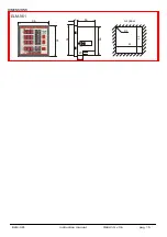
Страница 15: ...ELM 961 instruction manual IM441 U v0 6 pag 15 DIMENSIONS ELM 961 96 9 56 cut panel 96 96 R3 92 90 92 20...

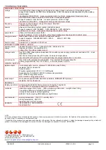
Страница 16: ...1 to 400 0 current inputs from 0 02 to 5A permanent overload 30 from external TA with secondary 5A primary programmable from 5 to 10000A auto consumption 0 5VA INPUTS OUTPUTS digital outputs Two outpu...

Отзывы: