background image


E L A N   H O M E   S Y S T E M S


VL10


© ELAN Home Systems   2011 • All rights reserved.

Page 7


Planning


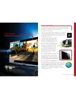
The VL10 can be installed and placed on almost any flat surface such as 
a desk, table or countertop, or easily mounted underneath a cabinet. 
Because it folds flat, the VL10 can be tucked neatly out of view when not 
in use.


When planning specific under cabinet installation locations for LCD 
Touch Panels, please keep the following tips in mind: 


When properly installed, nothing should be applying contact pressure to 
the touch panel except for the operator’s finger. If something is touching 
the touch screen window, a false signal can be generated causing the touch 
panel to respond incorrectly. 


Avoid installation in direct sunlight or strong ultraviolet light (such as grow 
lamps for plants). This can degrade or discolor the polyester film. 


Avoid installation over heat generating devices and/or in moist areas where 
condensation can form on the polyester film. Both heat and condensed 
moisture can affect touch screen performance. 


The touch panel/LCD assembly should not be mounted near electronics 
that emit radio frequencies or electromagnetic interference (such as CRT 
monitors, light dimmers, and some power supplies). 


Do not mount the VL10 outdoors or in areas exceeding its operating 
temperature range of -10°F (-23°C) to +115°F (+46°C). If the LCD display is 
over-heated or its temperature reduced below its recommended minimum, 
the liquid crystal polymer can be damaged and the display image may not 
recover. 

Содержание vl10

Страница 1: ...VL10 Tabletop Under Cabinet 10 Color Touch Screen INSTALLATION MANUAL...

Страница 2: ...comply with the limits for a Class B digital device pursuant to part 15 of the FCC Rules These limits are designed to provide reasonable protection against harmful interference in a residential instal...

Страница 3: ...roduction 3 Touch Screen Technology 3 Features 3 Package Contents 4 Movable Swivel Display 4 Power Button 6 Mini USB Port 6 Planning 7 System Wiring 8 Wiring 8 Video Termination Switch 9 Under Cabinet...

Страница 4: ...lor LCD Liquid Crystal Display screen Depressing the polyester film with a finger allows the film to touch the glass panel underneath generating a location signal that is read by the electronics The 1...

Страница 5: ...y pivots back 90 on a central axis as shown below in Figure1 2 it also pivots forward 45 from its central axis as shown in Figure1 3 The display rotates up to 330 from stop to stop about the vertical...

Страница 6: ...ELAN HOME SYSTEMS VL10 ELAN Home Systems 2011 All rights reserved Page 5 Figure 1 2 Back to Front Pivoting Display Figure 1 3 Display Rotation...

Страница 7: ...will come on and the VL10 will startup To turn the VL10 off press and hold the power button for approximately 5 seconds until the VL10 shut downs The second function is to toggle the back light off an...

Страница 8: ...uch panel to respond incorrectly Avoid installation in direct sunlight or strong ultraviolet light such as grow lamps for plants This can degrade or discolor the polyester film Avoid installation over...

Страница 9: ...ge 8 System Wiring Wiring The VL10 requires power Ethernet and optionally video connections The VL10 comes with a Precision Panel and a 12 Cable Assembly to simplify the installation See Figure 3 1 an...

Страница 10: ...o the VL10 Touch panel is to be looped back out of the panel to another Touch Panel or TV an F connector VIDEO OUT is provided The Video Termination Switch must be moved from the factory default to th...

Страница 11: ...source If you choose to power the VL10 locally you will need to purchase a PWR1 Cable Strain Relief The VL10 has a cable clamp system on the underside of the base cover along the rear edge After the c...

Страница 12: ...stall VL10 under a cabinet 1 Choose an appropriate mounting location underneath desired cabinet or shelf 2 Remove and remount the ELAN badge Remove 2 screws from rear panel location as shown in Figure...

Страница 13: ...length must protrude from underside of cabinet less than 0 5 inch See Figure 4 4 5 Using the provided VL10 Adhesive Backed Vinyl Mounting Template remove the protective backing material and carefully...

Страница 14: ...the underside of the VL10 Figure 4 4 Remove Feet 7 Make the required cable connections Power Ethernet and optional Video to the rear of the VL10 8 Install the 6 32 screws through the cabinet bottom t...

Страница 15: ...VIA Valet100 with no modifications to the cabinet Two extra holes are provided on the base plate of the VL10 that will allow the mounting holes to align exactly when upgrading from a VIA Valet64 The...

Страница 16: ...o equipment sold by but not manufactured by ELAN the warranty obligations of ELAN shall in all respects conform to the warranty actually extended to ELAN by its supplier The foregoing warranties do no...

Отзывы: