12
•
Visually Check for any damaged tube or wires
•
If the car with Protective barrier .Check for damage and correct installation.
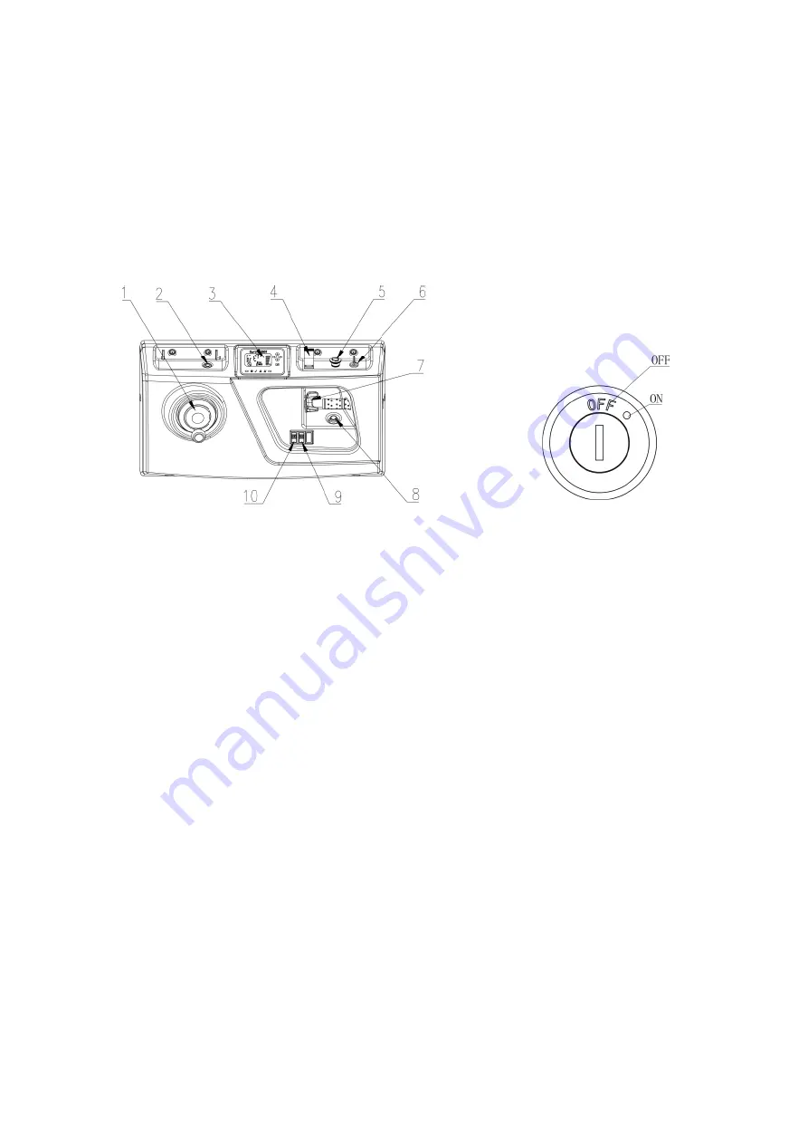
7.The Schematic diagram of Operating Mechanism
Fig 7 Operating console Fig 8 Key Switch
Figure 7.1 the steering wheel, which controls the steering of the truck by
rotating the steering wheel.
Figure 7.2 is emergency lowering button, When 7.4(as figure shows) lifting &
lowering joystick fails, Press the emergency lowering button to safety lower the
cockpit to the bottom
Firgue7.3 is Curtis instrument, displaying vehicle information.
Figure 7.4 is lifting & lowering joystick , which is used to control the lifting and
lowering of the mast and the cockpit.
Figure 7.5 is Emergency stop switch
Figure 7.6 is Key switch ,Control truck power connection and disconnection
Figure 7.7 Accelerator , Used to control the forward and backward of the truck,
and control the driving speed by controlling the degree of rotation
Figure 7.8,Horn button
Figure 7.9 Headlight switch
Figure 7.10 Waring light switch
Содержание EOP68
Страница 1: ...SPECIFICATION ORDER PICKER EOP68...
Страница 8: ...4 3 2Truck schematic diagram Model parameters Figure 2 Schematic diagram...
Страница 32: ...28 13 Electrical Schematic diagram...
Страница 33: ...29 14 Hydraulic Schematic diagram This manual final interpretation retained by manufacturers...


