background image

Содержание ER7-700

Страница 1: ...ER7 700 Mechanical Operation and Maintenance Manual for Industrial Robot EFORT INTELLIGENT EQUIPMENT CO LTD HOT LINE 86 400 0528877 ...

Страница 2: ......

Страница 3: ...give EFORT robot or other objects around cause property damage This statement and the manual are the latest version as of this batch of products before leaving the factory Please follow the official website of www efort com cn for the updated information This manual is only used as a guide for the normal operation of the product During the use of the product EFORT will not be liable for personal i...

Страница 4: ......

Страница 5: ...NSTRUCTION 7 2 1 ROBOT SYSTEM CONFIGURATION 7 2 2 OPEN BOX TO CHECK 7 2 3 MACHINE BODY NAMEPLATE 8 2 4 COMPOSITION OF THE BODY AND THE DIRECTION OF EACH AXIS 9 2 5 HARD LIMIT OF EACH AXIS OF MECHANICAL BODY 10 2 6 ROBOT PERFORMANCE PARAMETERS 11 2 7 ALLOWABLE LOAD OF WRIST 13 2 7 1 Allowable handling weight 13 2 7 2 Allowable maximum static load torque 13 2 7 3 Allowable maximum moment of inertia ...

Страница 6: ... 3 4 INTEGRATED APPLICATION INSTALLATION INTERFACE 21 CHAPTER 4 INSPECTION AND MAINTENANCE 26 4 1 PREVENTIVE MAINTENANCE 26 4 1 1 Daily inspection 26 4 1 2 Quarterly inspection 26 4 1 3 Annual inspection 27 4 1 4 Check every 2 years 27 4 2 OVERHAUL OF MAIN BOLTS 27 4 3 CONVEYOR MAINTENANCE 28 4 4 ROBOT MAINTENANCE AND USE AREA 32 4 5 ZERO CALIBRATION 33 4 5 1 Zero calibration method 33 4 5 2 Mecha...

Страница 7: ...ER7 700 Industrial Robot Mechanical Use and Maintenance Manual III B SPARE PARTS LIST 35 ...

Страница 8: ......

Страница 9: ...ed within the allowable weight and torque If you do not comply with the regulations that allow the weight and torque to be carried it will cause abnormal movements or premature damage to mechanical components 6 It is forbidden to disassemble and operate the parts not covered by the maintenance manual The robot is equipped with various self diagnosis functions and abnormality detection functions an...

Страница 10: ...o stop or escape the robot that moves suddenly so the following best countermeasures should be implemented to avoid such accidents In order to abide by these principles it is necessary to fully understand the precautions described below and implement them effectively 1 1 2 Safety countermeasures of robot body The design of the robot should remove unnecessary protrusions or sharp parts use material...

Страница 11: ...ective structure should be adopted Even if the power supply of the end effector or the supply of compressed air is cut off there will be no accident of the installation being released or flying out Damage A fail safe protective structure should be adopted Even if the power supply of the end effector or the supply of compressed air is cut off there will be no accident of the installation being rele...

Страница 12: ...n also cause accidents When an abnormality is found the emergency stop button should be pressed immediately This requirement must be thoroughly implemented According to the installation site and the content of the operation the operation regulations and check list of the robot s starting method operation method and solution method when abnormality occurs should be compiled And work in accordance w...

Страница 13: ...d tools are forgotten which can cause accidents such as falls To ensure safety start with rectification 1 2 Robot transfer transfer sale When transferring transferring and selling robots you must ensure that the robot related documents such as the machine manual electrical maintenance manual and robot programming manual are transferred to the new user When transferring transferring or selling abro...

Страница 14: ...oard components etc before discarding Sharp parts such as cracks or cuts and wires may cause injury After the cable and external wiring are removed from the connector and junction box do not disassemble it further and discard it Otherwise your hands or eyes may be injured due to conductors When carrying out discarding operations please be careful not to get pinched or injured Waste products should...

Страница 15: ...ustrial robot system configuration 2 2 Open box to check 1 Before unpacking please confirm whether the product packaging is intact 2 After unpacking please confirm whether the robot accessories are complete and whether the model is consistent with the order If you find missing or wrong parts please contact the supplier in time Unpacking list Name Model Quantity Unit Remarks Robot body ER7 700 1 PC...

Страница 16: ...y The nameplate contains information such as the corresponding product model weight voltage production number and production date As shown in Figure 2 2 below Figure 2 2 Nameplate of the robot Electric cabinet body power and coding code EC M6 SC PB 1 PC Cabinet power cord 1 PC Installed on the electrical cabinet Body IO line 1 PC Accessories bracket gasket 1 SET Installed on the electrical cabinet...

Страница 17: ...of six parts Base Frame Arm Gear Box Wrist 1 and Wrist 2 The joints of the mechanical body are driven by servo motors and the joints cooperate with each other to adjust the position and posture of the robot end in space The name of each component of the mechanical body and the direction of each axis are shown in Figure 2 3 Figure 2 3 ER7 700 mechanical body components ...

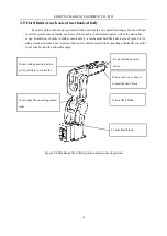
Страница 18: ...her ensure safety a mechanical hard limit device see Figure 2 4 is also provided on some axes to prevent the robot control system from operating abnormally when the robot runs beyond the allowable range Figure 2 4 Mechanical hard limit position and zero mark position J2 axis depends on casting contact limit J3 axis limit block J4 axis infinite position device set by software to control the range o...

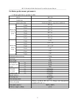
Страница 19: ...xis 720 sec Maximum motion range J1 axis 170 J2 axis 80 135 J3 axis 70 195 J4 axis 190 J5 axis 120 J6 axis 360 Maximum radius of activity 713mm Hand load 7Kg Body weight 38Kg Wrist allows maximum static torque J4 16Nm J5 16Nm J6 9Nm Allowable maximum inertia of wrist J4 0 45Kg m2 J5 0 45Kg m2 J6 0 14Kg m2 Repeat accuracy 0 02mm Robot base size 200 200mm Ambient temperature 0 45 C Relative humidity...

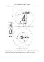
Страница 20: ...t workspace Figure 2 5 Robot motion range diagram Note The working space shown in this figure is the maximum that can be achieved in theory The actual operation will be affected by the installation method There will be changes in actual operation ...

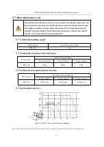
Страница 21: ...than the allowable value normal operation cannot be guaranteed 2 7 1 Allowable handling weight 2 7 2 Allowable maximum static load torque Robot model Allow static load torque J4 axis rotation J5 axis rotation J6 axis rotation ER7 700 16Nm 16Nm 9Nm 2 7 3 Allowable maximum moment of inertia Robot model Allowable moment of inertia J4 axis rotation J5 axis rotation J6 axis rotation ER7 700 0 45 kg m2 ...

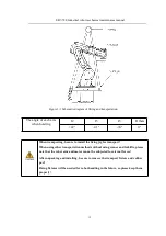
Страница 22: ...ling In addition after the device is assembled protective measures such as a protective cover should be taken to avoid damage to the wiring by operators forklifts etc 3 1 2 Handling method In principle use cranes and other machinery for hoisting When hoisting the sling installation method is as shown in the figure below Adjust the robot joints to the position shown in the figure When hoisting in o...

Страница 23: ...sing other transportation methods without using cranes and forklifts please note that the robot arm and motor cannot be subjected to external forces After unpacking and installing be sure to remove the transport fixture and rubber pad Fixing fixtures will be needed for robot handling in the future so please keep them properly The angle of each axis when hoisting J2 J3 J5 Others 22 41 74 0 ...

Страница 24: ...dustrial robot because the operator is in danger of contacting the robot there must be Safety measures such as protection In order to avoid damage to the equipment during the operation of the robot personal injury to the operator and the surrounding people please be sure to set up a safety bar with safety settings such as interlocking doors Note The standard of GB11291 Robots for Industrial Enviro...

Страница 25: ...e dimensions Note When installing the robot body the following precautions should be strictly followed to avoid deformation of the rotating base 1 The flatness of the robot mounting panel should be controlled within 0 2mm 2 The relative height error of the mounting surface of the robot mounting panel should be within 0 2mm 0 1mm ...

Страница 26: ...ing the operation of the equipment please fully fix and prevent loosening according to the method shown in Figure 3 4 Robot Installation Example Figure 3 3 Ground installation Too long or too short screws to fix the robot base will cause bad fixing accidents The connection strength of chemical bolts depends on the strength of concrete When the strength of concrete is insufficient it can be strengt...

Страница 27: ...the safety of the robot s work the strength of the screws used is 12 9 and a drop device must be installed Figure 3 4 Tilt installation 3 2 5 Suspension installation To ensure safety the following precautions are required when installing upside down or wall 1 1 Install an anti fall safety device as shown in Figure 3 6 below 2 The screws for connection need to be 12 9 strength screws and the tighte...

Страница 28: ...should meet the requirements Robot environmental conditions Environmental conditions Working condition Storage and transportation conditions Ambient temperature 0 45 40 55 Relative humidity 80 40 93 40 Atmospheric pressure 86 106 kPa vibration Less than 0 5G 4 9m s2 Others No corrosive gas note Notes For the robot to be used if there is strong vibration a lot of dust cutting oil splash or other ob...

Страница 29: ...xed surface you need to add a gasket on the end flange surface the gasket is already installed on the packaging bracket or tooling design When you need to increase the step design refer to the following figure Robot external interface size Pictured Remarks End mounting flange dimension drawing Figure 3 6 End installation size End tool dimension drawing Figure 3 7 End tool size Dimension drawing of...

Страница 30: ...EFORT INTELLIGENT EQUIPMENT CO LTD 22 2 End tool size Figure 3 7 End tool dimensions ...

Страница 31: ...ER7 700 Industrial robot mechanical maintenance manual 23 3 Other auxiliary interface Figure 3 8 Dimensions of external parts installed on the motor base ...

Страница 32: ... the maximum allowable air pressure is 0 8MPa The external signal line is 2 leads The corresponding external signal line socket has been equipped in the spare parts Figure 3 10 Standard gas circuit schematic diagram standard Definition of X60 connector on ER7 700 robot body side No 60 PIN Signal definition Remarks 1 1 DI8 2 2 DI9 3 3 DI10 4 4 DI11 5 5 DI12 6 6 DI13 7 7 DO14 8 8 DO15 9 9 24VP 10 10...

Страница 33: ...gram of the solenoid valve gas circuit optional Figure 3 12 Air circuit interface diagram Note In the standard specifications only AIR1 and AIR2 have built in straight trachea Solenoid valve and check valve are installed in the specified position in the built in solenoid valve option ...

Страница 34: ...nd whether there is abnormal jitter 3 Air cooling inspection Check whether the fan behind the control cabinet is well ventilated 4 Inspection of pipeline accessories Whether it is complete and complete whether it is worn whether there is corrosion 5 Peripheral electrical accessories inspection Check the external circuit of the robot whether the button is normal 6 Leak check Check if there is any l...

Страница 35: ...ing screws the robot body mounting screws and the screws removed due to maintenance etc All screws exposed outside the robot should be tightened For the installation torque please refer to the appendix screw tightening torque table And apply the corresponding fastening glue or sealant 4 2 Overhaul of main bolts Table 4 5 Main screw inspection locations No Check parts No Check parts 1 For robot ins...

Страница 36: ...r prepared tools No contents of operation 1 Prepare for operation so that it can be operated manually 2 Place the robot as shown in the figure 3 Remove the cover Remove the 6 M4 screw of the 4 axis cover and tighten the torque to 3 4Nm Remove the 5 axis cover 7 M4 screws tightening torque 3 4Nm Remove the 6 M4 screw of the 3 axis cover and tighten the torque to 3 4Nm Remove the 2 axis cover 7 M4 s...

Страница 37: ...ensity 0 041Kg m Initial tension frequency of J2 axis conveyor belt 140 150Hz Center distance 127 5mm Conveyor linear density 0 041Kg m Initial frequency of J4 axis conveyor belt 240 260Hz Center distance 49 5mm Conveyor linear density 0 013Kg m Initial tension frequency of J5 axis conveyor belt 100 120Hz Center distance 144mm Conveyor linear density 0 013Kg m ...

Страница 38: ...yer falls off and the color is whitish The texture of the tooth cloth becomes inconspicuous Abnormal item Appearance Abnormal wear of teeth Root crack Tooth loss Abnormal wear Note It is normal for the side to be cut like a knife cracks on the side of the belt Tooth The tooth cloth is worn exposing the rubber Tooth width narrows cracks Exposed core Abnormal wear and tear dropped core wire Rounded ...

Страница 39: ...otor mounting plate 6 Remove the conveyor belt and replace it with a new one 7 Tighten the fixing bolts of the motor mounting plate Use a spring scale to pull the motor mounting plate to the specified tension position and tighten the bolts 8 Remove the tool from the arm and restore power 9 Zero calibration of the replaced mechanical shaft When replacing the conveyor belt be sure to fix the mechani...

Страница 40: ...safety latch etc are provided on the safety door and the robot stops after opening the safety door Safety carpets or photoelectric switches should be installed on the floor so that when the operator enters the robot s range of motion the buzzer and photoelectric switch will sound an alarm to stop the robot s movement to ensure the safety of the operator The height of the safety fence is not less t...

Страница 41: ...ommon problems and solutions to these problems Software zero calibration The laser tracker needs to be used to establish the coordinate system of each joint of the robot and the system encoder reading is set to zero The software calibration is more complicated and needs to be operated by the professional staff of our company Mechanical zero point calibration alignment calibration Rotate the markin...

Страница 42: ...flange material please refer to the notes in the table to apply Screw 12 9 Tightening torque cast iron Tightening torque cast aluminum M3 2 0 18 2 0 18 M4 4 5 0 33 4 0 33 M5 9 01 0 49 7 35 0 49 M6 15 6 0 78 12 4 0 78 M8 37 2 1 86 30 4 1 86 M10 73 5 3 43 59 8 3 43 M12 128 4 6 37 104 6 37 M14 204 8 10 2 180 10 2 M16 318 5 15 9 259 15 9 ...

Страница 43: ...or 10900020063 1 J5 servo motor 10900020065 1 J6 Table 2 Reducer name Material code Quantity Remarks Reducer 10800011780 1 J1 Reducer 10800012257 1 J2 Reducer 10800012255 1 J3 Reducer 10800010473 1 J4 Reducer 10800000127 1 J5 Reducer 10800010474 1 J6 Table 3 Sealants and others name Material code Quantity Remarks Flat sealant THREEBOND 1110F 1 Thread Fastener THREEBOND 1374 1 detergent THREEBOND 6...

Страница 44: ...ENT CO LTD 36 Table 4 Synchronous belt material codes name Material code Quantity Remarks Synchronous belt 10300012999 1 J2 Synchronous belt 10300013000 1 J3 Synchronous belt 10300013082 1 J4 Synchronous belt 10300012998 1 J5 ...

Страница 45: ... etc of this product are subject to change without modification without notice Technical data and illustrations are for reference only and the right to change is reserved 埃夫特智能装备股份有限公司 EFORT INTELLIGENT EQUIPMENT CO LTD 中国安徽省芜湖市鸠江经济开发区万春东路 96 号 No 96 Wanchun Road Jiujiang Economic Development Zone Wuhu Anhui China 网址 http www efort com cn ...

Отзывы: