ER7-700 Industrial robot mechanical maintenance manual
25
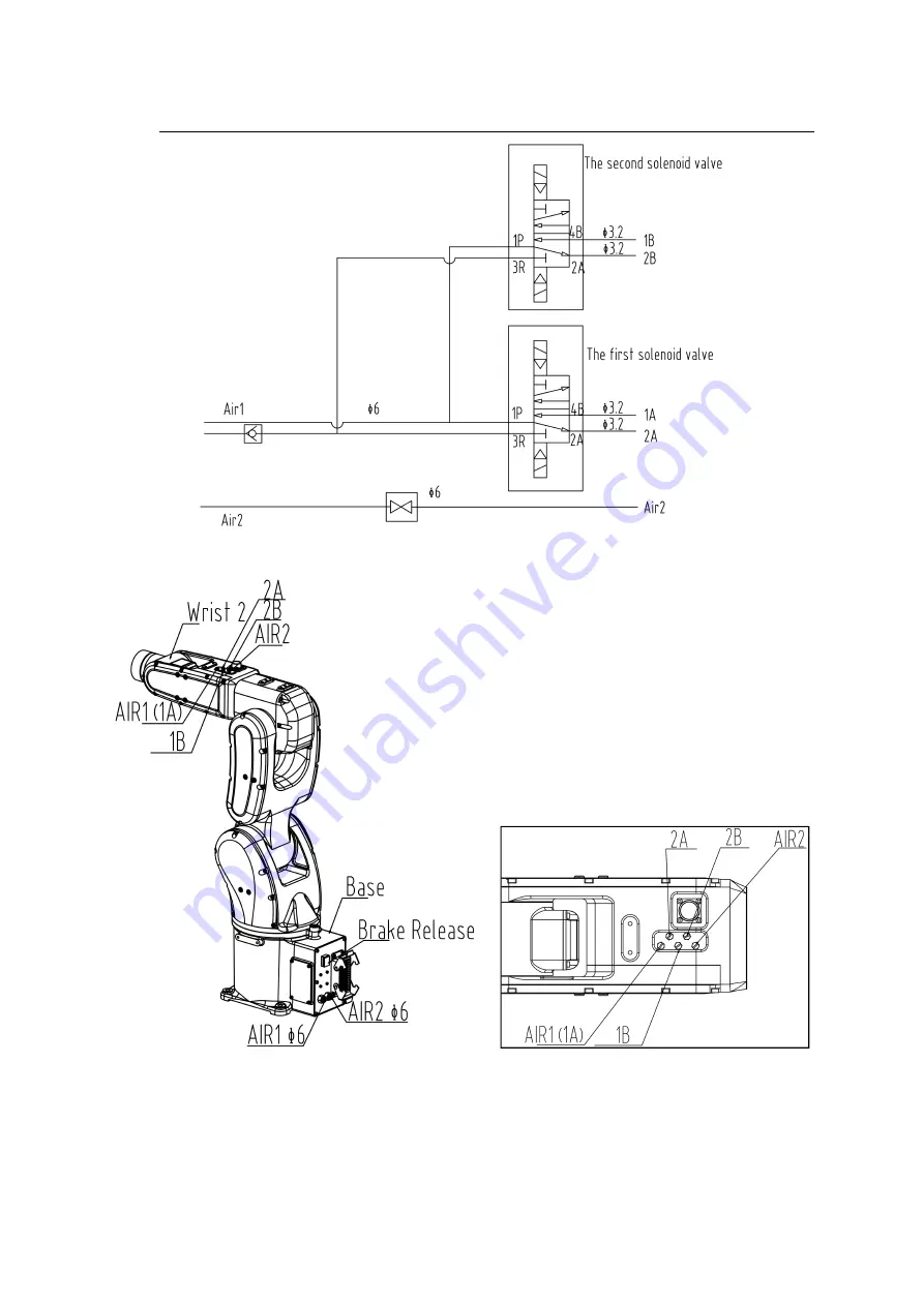
Figure 3-11 Schematic diagram of the solenoid valve gas circuit (optional)
Figure 3-12 Air circuit interface diagram
Note: In the standard specifications, only AIR1 and AIR2
have built-in straight trachea.
Solenoid valve and check valve are installed in the specified
position in the built-in solenoid valve option.
Содержание ER7-700
Страница 2: ......
Страница 4: ......
Страница 7: ...ER7 700 Industrial Robot Mechanical Use and Maintenance Manual III B SPARE PARTS LIST 35 ...
Страница 8: ......
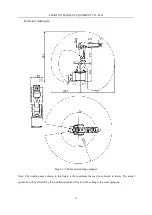
Страница 30: ...EFORT INTELLIGENT EQUIPMENT CO LTD 22 2 End tool size Figure 3 7 End tool dimensions ...

