background image


10 


ADJUSTING THE RESISTANCE


To adjust the tension level, turn the 

Adjustment Knob (C) 

on the 

Hydraulic Cylinder 

(No.10)

 to the desired level. The tension levels range from Level 1 to Level 12, with 

Level 1 being the lowest resistance. The number pointing to the

 Adjustment Knob (C)


by the 

Arrow (B) 

is the resistance value of the current 

Hydraulic Cylinder (No.10)

 
NOTE:

 Please do not adjust the resistance of the 

Hydraulic  Cylinder  (No.10)

 during 

operation to avoid injury and damage to the machine. 


WARNING:


The 

Hydraulic Cylinder (No.10)

 on this rower is designed to be used up to 20 minutes 

per exercise session. Allow at least 20 minutes in between sessions for the 

Hydraulic 

Cylinder (No.10)

 to properly cool down.


Caution:  The 

Hydraulic  Cylinder  (No.10)

  can  generate  excessive  heat  after  long 

period of use, making it unsafe to touch. Allow the 

Hydraulic Cylinder (No.10)

 to cool 

before moving the rower.


Содержание RW032

Страница 1: ...G MACHINE MODEL NO RW032 IMPORTANT Read all instructions carefully before using this product Save this manual for future reference EXERCISE EQUIPMENT QUESTIONS Contact customer service at service zoov...

Страница 2: ...ult use only Keep children and pets away from the machine DO NOT leave children unattended in the same room with the equipment 4 Use the equipment on a solid flat level surface with a protective cover...

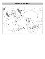
Страница 3: ...3 EXPLODED DRAWING...

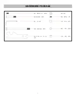
Страница 4: ...4 HARDWARE PACKAGE...

Страница 5: ...12 Refer to No 55 41 Bolt M8 115 20 S 5 2 13 Refer to No 57 42 Bolt M8 120 20 S 5 1 14 Spanner S 10 13 17 19 1 43 Screw M8 15 S 5 13 15 Cir Clip 12 2 44 Screw M6 15 2 16 Adjusting Screw M6 45 2 45 Was...

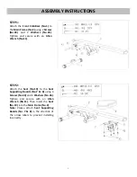
Страница 6: ...th an Allen Wrench No 11 STEP 2 Attach the Seat No 19 to the Seat Supporting Boards No 7 8 using 4 Screws No 43 and 4 Washers No 45 Tighten and secure with an Allen Wrench No 11 Then Insert the Seat N...

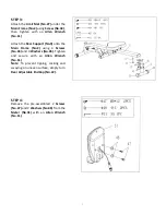
Страница 7: ...ort No 3 onto the Main Frame No 2 using 4 Screws No 43 and 4 Washers No 45 Tighten and secure with an Allen Wrench No 11 Note To prevent tipping rocking and swaying on uneven surface simply turn Rear...

Страница 8: ...er Support No 56 using 2 Screws No 47 and 2 Washers No 48 that were removed then tighten with an Allen Wrench No 11 STEP 6 Connect part E with part F Attach the Meter Support No 56 onto the Main Frame...

Страница 9: ...ough the Pedals No 23 and into the Meter Support No 56 NOTE The Pedals No 23 should rest on the Bolts No 53 STEP 8 Attach the 2 Handlebars No 6 into the Rotating Armrest No 4 using 2 Bolts No 55 4 Was...

Страница 10: ...inder No 10 NOTE Please do not adjust the resistance of the Hydraulic Cylinder No 10 during operation to avoid injury and damage to the machine WARNING The Hydraulic Cylinder No 10 on this rower is de...

Страница 11: ...49 remove the velcro end of the strap from the mesh side by pulling it upward then to the left Once removed you may increase the opening of the Pedal Strap No 49 by pulling the mesh end up and to the...

Страница 12: ...lly scan through all the functions played on the bottom of the meter TIME The total working time will be shown when starting exercise CAL CALORIES The Computer will display total calories burns when s...

Отзывы: