background image

Software Overview

Document ID: OMM-00165 Rev. C

Pro 32r Operations Guide

51

4.2.3

Left-Right Calibration Dialog

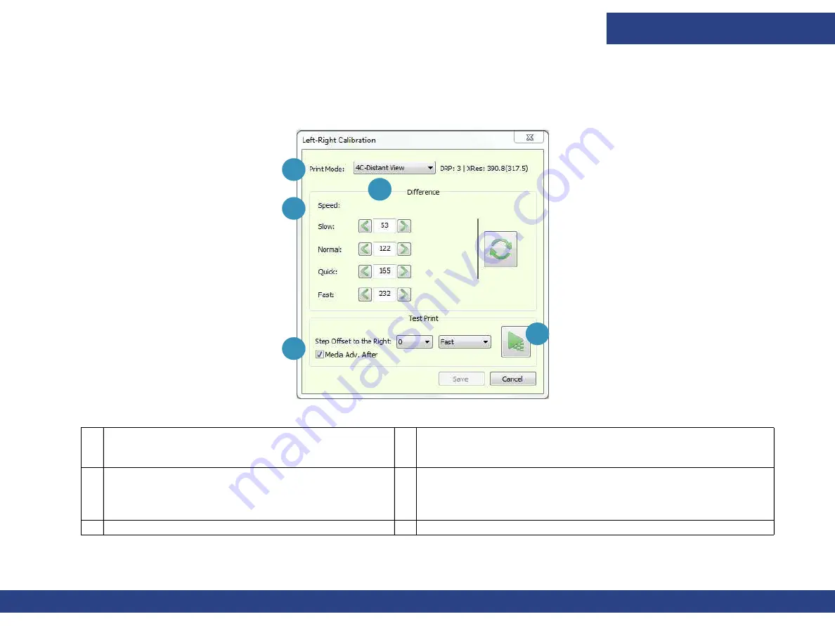
This dialog sets the position of heads firing during bi-directional printing, in units of pixels. Opens via the Left-Right icon on the Front-

end window’s Control Panel or from the Calibrations options in the Tools menu.

Figure 4-5  Left-Right Calibration

1

Print Mode

 – Select the Print Mode to calibrate.

3

Speed 

-

 Carriage speed in which you are printing: Slow, Normal, 

Quick, and Fast.

2

Difference 

– There are four optional carriage 

speeds for each print mode. Speed is  predefined in 

the Print Mode list and is usually set to Fast. Make 

sure to insert values in the  correct spin box.

4

Set the Step Offset to the Right 

– Sets the location of the 

pattern on the media width.

5

Test Print 

– Print the Left-Right Calibration test pattern.

1

2

3

4

5

Содержание Pro 32r

Страница 1: ...Pro 32r Printers Operations Guide ...

Страница 2: ... 562 6 219 155 6 219 659 6 222 641 6 224 048 6 225 974 6 226 419 6 238 105 6 239 895 6 256 108 6 269 190 6 271 937 6 278 901 6 279 009 6 289 122 6 292 270 6 299 063 6 310 697 6 321 133 6 327 047 6 327 050 6 327 052 6 330 071 6 330 363 6 331 899 6 337 746 6 340 975 6 341 017 6 341 018 6 341 307 6 347 256 6 348 978 6 356 359 6 366 918 6 369 895 6 381 036 6 400 443 6 429 949 6 449 393 6 457 823 6 476...

Страница 3: ...ons Guide iii Revision History Ver Date Description Request A 05 10 2019 Initial release DR 5347 B 07 19 2019 New doc style Updated image and description for Fig 3 7 DR 5847 C 12 19 2019 Corrected description of 2 3 7 3The Safety Laser Beam DR 6093 ...

Страница 4: ...ont end Window Control Panel 46 4 3 Front end Window One Job 52 4 4 Front end Window Queue 53 4 5 Front end Window View Menu 55 4 6 Front end Window Tools Menu 63 5 0 PRINTER SETUP 76 5 1 Print Table 76 5 2 Printer Carriage 77 5 3 Cleaning Print Heads 84 5 4 Advanced Fine Tuning 93 5 5 Other Preparations 96 6 0 PRINTER OPERATIONS 105 6 1 EFI Pro 32r Start Up Procedures 105 6 2 Defining Job Setting...

Страница 5: ...Introduction Document ID OMM 00165 Rev C Pro 32r Operations Guide 5 1 0 Introduction Operations Guide ...

Страница 6: ...ion EFI Inkjet provides an educational support system that assists new and experienced operators to develop and maintain skills Go to http inkjet support efi com training for training information Congratulations You have purchased the finest super wide format digital ink jet printing system in the world EFI VUTEk h Series printers are premium digital ink jet printers with vivid full color printing...

Страница 7: ...r printer or accessories 1 5 Customer Support Web Site North South Americas Europe Middle East Africa Asian Pacific APAC Customer Care U S 855 EFI 4HLP 855 334 4457 31 20 658 8070 1 650 357 4790 EuroInk efi com Canada Mexico South America 1 650 357 4790 Technical Support https inkjet support efi com US Canada 855 EFI 4HLP 855 334 4457 32 2 749 94 50 65 6221 2765 Mexico South America 1 412 690 4321...

Страница 8: ...Introduction Document ID OMM 00165 Rev C Pro 32r Operations Guide 8 2 0 Safety Operations Guide ...

Страница 9: ...when a remote connection is required by EFI s Service Engineer Once the remote connection is no longer required it must be canceled Do not install any Antivirus program on the PRO 32R PC since it consumes between 10 and 20 of the RAM and as a result reduces the printer s performance Do NOT connect any kind of USB memory stick to the PRO 32R PC Non compliance with the above points may cause malfunc...

Страница 10: ...ty Labels Components Sign Component Action Action Action Main Power Switch Switch printer on off Emergency Stop Button Press to immediately to halt printer operation Emergency Stop Cord Pull to immediately turn off the printer Automatic Cutting Device Surface Label 1 Do not place hands near cutting edges Label 2 Keep hands clear Label 3 Keep covered when appropriate ...

Страница 11: ...trical Hazard Label 2 Do not touch Keep your distance Label 3 Disconnect from the main supply before touching this component or wiring Hot Surface Label 1 Hot surface Label 2 Do not touch before protection is applied Label 3 Read the manual regarding safe contact Moving Parts Label 1 Moving parts Label 2 Do no open the guards until moving parts stop Label 3 Keep hood closed during printing Sign Co...

Страница 12: ...and shafts while the printer is operating Label 3 Read the manual Inhalation of Hazardous Gases Label 1 Inhalation of hazardous gases or vapors Label 2 Do not unplug the printer or the fan Label 3 Ensure that the printer s ventilator is working Beware of the suction Danger of Splashing Ink Label 1 Danger of splashing ink Label 2 Keep clear of the area while printer is printing Label 3 Avoid contac...

Страница 13: ... Label 1 Keep hands fingers out of the printer Label 2 Keep clear of moving parts Label 3 Read the manual Pressing Device Label 1 Keep hands fingers out of the printer Label 2 Keep clear of moving parts Label 3 Read the manual Danger of Crushing Legs Label 1 Keep your feet away from the printer Label 2 Wear appropriate footwear Label 3 Read the manual Sign Component Action Action Action ...

Страница 14: ...es all the cables and pipes between the PC ink system and the carriage During printing the carriage moves continuously along the chassis 2 3 2 The Cover The cover is located at the front of the printer its function is to protect user from UV rays and from contact with the moving carriage It opens and closes manually 2 3 Potential Hazards Warning Contact between the moving carriage and a foreign ob...

Страница 15: ...de 15 Open the Cover Pull handle to lift the cover Close the Cover With one hand push the lift cylinder as you push the cover down with your other hand NOTE The printer does not operate unless the cover is closed Cover Open Figure 2 2 Lift Cylinder Figure 2 3 ...

Страница 16: ...zone of 1m around the printer PRESS ROLLER Do not place your hand near the revolving press roller and shaft It can get caught and crushed As a safety feature the printer requires that the operator use both hands to press two buttons to activate the rollers A safety label near those buttons instructs users to make sure that the rollers are not obstructed Rolling Media Backwards Rollers can pull and...

Страница 17: ...red by electricity 1 phase 230VAC The PC The motor drivers The UV bulb assembly In addition within the printer AC voltage is are converted to DC voltages of 5V 24V and 48V and distributed to various points Contact with any of these voltages may cause electrical shock and burns Electrical hazard is minimized as follows Circuit breakers Over current and over voltage activate a circuit breaker at the...

Страница 18: ...ith the following emergency stops Emergency buttons Emergency cord Laser beam 2 3 7 1 The Emergency Stop Buttons The printer is equipped with four emergency stops front right and left plus rear right and left Push the Emergency button to immediately stop the printer When pushing the Emergency button The printer stops the power is cut off and the pinch rollers open To activate or reactivate printer...

Страница 19: ... Pro 32r Operations Guide 19 2 3 7 2 The Emergency Cord Printer is equipped with two emergency cords front and rear Pull cord in case of emergency to immediately stop printer Figure 2 5 Emergency Stop Cord Front Emergency Stop Cord Rear ...

Страница 20: ... The Safety Laser Beam The safety laser beam is designed to avoid potential hazard from the tension and pinch rollers Interruption or penetration through the laser beam during printing stops the printer Figure 2 6 Laser Source and Mirror Front Laser Source and Mirror Rear ...

Страница 21: ...Introduction Document ID OMM 00165 Rev C Pro 32r Operations Guide 21 3 0 Hardware Overview Operations Guide ...

Страница 22: ...ide 22 This chapter describes the major assemblies and sub assemblies of the EFI Pro 32r Wide Format printers to familiarize you with their most important components 3 1 General Description 3 0 Hardware Overview Figure 3 1 Ink Systems Area Printing Area Operating Area ...

Страница 23: ...ardware Overview Document ID OMM 00165 Rev C Pro 32r Operations Guide 23 Figure 3 2 Printer s Carriage Home Position Printer s Cover Printer s Monitor Media Output Operator s Station Access Printer s PC ...

Страница 24: ...ro 32r Operations Guide 24 The following figure shows the rear of the printer NOTE The location of Printer parts assumes that the user is facing the Printer whether at front back or sides Figure 3 3 Air Shaft Air Shaft Control Main Switch Air Outlet ...

Страница 25: ... Shaft The media is loaded on the rear air shaft and collected on the front air shaft The rubber bladders on the air shaft expand when filled with air in order to hold the loaded media core in place There is a ruler on each end of the air shaft to show the location of the media edge relative to the shaft Figure 3 4 Rubber Bladder Ruler Air Inlet Air Outlet 3 2 Printer Rollers and Shafts ...

Страница 26: ... the chuck to release or reload the shaft roller then push the chuck sideways 2 Close the chuck and put it back into the closed position 3 Load the media then fill air into the shaft by inserting the air gun into the air inlet 4 To release the media release air by pressing the air outlet refer to for more details Figure 3 5 Chuck Open Chuck Closed ...

Страница 27: ...ntainer White Ink Container Figure 3 6 The Pro 32r has six ink tanks located in the rear right cabinet There are the five print inks cyan magenta yellow black and white and a waste ink tank to store ink residue collected from the waste tray 1 Fill each ink tank before it is completely empty 2 Empty the waste ink container before it is completely full The ink level of the five prime ink tanks conta...

Страница 28: ...erview Document ID OMM 00165 Rev C Pro 32r Operations Guide 28 3 3 2 Ink Pumps and Filters Figure 3 8 Ink Pump Connectors Filter Ink Pump Two way Solenoid Valve PP Pump NP Pump Filter Solenoid Valve Pump Connector ...

Страница 29: ...Hardware Overview Document ID OMM 00165 Rev C Pro 32r Operations Guide 29 3 3 3 Carriage Ink System Figure 3 9 Overflow Sensors Air Release Valves Secondary Ink Tanks ...

Страница 30: ...re Overview Document ID OMM 00165 Rev C Pro 32r Operations Guide 30 3 3 4 Waste Ink Tray Excess ink from the print heads is collected in the waste ink tray and drained into the waste ink container Figure 3 10 ...

Страница 31: ...erview Document ID OMM 00165 Rev C Pro 32r Operations Guide 31 3 3 5 Ink System and Print Head Configuration The Print Head configuration Figure 3 11 White Yellow Cyan Magenta Black Black Magenta Cyan Yellow White ...

Страница 32: ...e Overview Document ID OMM 00165 Rev C Pro 32r Operations Guide 32 3 4 Pneumatic System Figure 3 12 Air Supply Port Air Pressure Regulators Five Way Solenoid Valve Main Back Infeed Roller Front Outfeed Roller ...

Страница 33: ...s of media Media Infeed Outfeed Roller bar psi Air Shaft rpm Tension Settings Vacuum Settings Option Front Outfeed Rear Infeed Front Rear Banner 1 6M 2 8 bar 42 psi 2 4 bar 35 psi 20 rpm 25 rpm 30 70 These values are approximate Small deviations are OK Banner 2 2M 2 4 bar 35 psi 2 4 bar 35 psi 20 rpm 25 rpm 30 70 Banner 3 2M 2 8 bar 42 psi 2 4 bar 34 psi 20 rpm 25 rpm 30 70 Sticker 1 4M 2 8 bar 42...

Страница 34: ...Figure 3 13 Rear Air Gun Inlet Figure 3 14 Front Air Gun Inlet Hardware Overview Document ID OMM 00165 Rev C Pro 32r Operations Guide 34 3 4 2 Gun Air Joint ...

Страница 35: ... 32r Operations Guide 35 The electric panel is located at the rear left side of the printer Figure 3 15 PLC Driver Controller Y T Axis X Axis Y Axis Motor Main Power Circuit Breaker Switch See Figure 3 16 Servo Driver 3 5 Electric Motion Control Panel ...

Страница 36: ...dware Overview Document ID OMM 00165 Rev C Pro 32r Operations Guide 36 Caution Improper use of the power and electrical connections can endanger your life Do not touch any of electric or electronic components without specific permission from an EFI Technician ...

Страница 37: ...t head Apply enough vacuum to prevent the ink from dripping through the print heads but also keep all the nozzles shooting properly See the pressure table below to determine the correct pressure for your jobs Adjust ink vacuum level in the FE Preferences Dialog Vacuum Pressure is displayed on the carriage and the I O control 3 6 Vacuum System White CMYK Figure 3 17 ...

Страница 38: ...rameter Value Unit Negative Pressure Color 3 8 kPA Negative Pressure White 4 0 kPA Positive Pressure Time Color 0 5 Seconds Positive Pressure Time White 0 5 Seconds Main Air Pressure 4 5 6 0 Bars Negative Pressure Color 4 3 3 kPA Negative Pressure White 4 5 3 8 kPA Figure 3 18 ...

Страница 39: ...Hardware Overview Document ID OMM 00165 Rev C Pro 32r Operations Guide 39 3 6 2 Print Table Vacuum System The print table vacuum motor is located at the bottom right of the printer Figure 3 19 ...

Страница 40: ...t a low temperature thus enabling printing on a vast range of media types including heat sensitive media Figure 3 20 Shown From Side of Carriage Carriage Ionizer The ionizer shown in Figure 3 20 neutralizes the electrostatic charge that accumulates and prevents mist from accumulating on the media Figure 3 20 shows one of the printer s two ionizers Each ionizer is located adjacent to a LED lamp uni...

Страница 41: ...dia Single or Multi roll printing Width wider media use lower vacuum Weight heavier media use lower vacuum Polyethylene PE Work with wings UP See Air Pressure Gauges for recommended vacuum values 3 9 Front Control Buttons Vacuum Knob Figure 3 21 1 Open closes pinch roller 3 Controls vacuum level of the print table See Vacuum Regulator 5 Turns light on print table on off 2 Raise lowers wings 4 Turn...

Страница 42: ...rol Buttons Tension Knob Hardware Overview Document ID OMM 00165 Rev C Pro 32r Operations Guide 42 Controls Arrows Sets the tension Rev Reverse Fwd Forward Stop Stops spinning Knob Sets spinning speed 3 10 Roll Tension Control ...

Страница 43: ...rview Document ID OMM 00165 Rev C Pro 32r Operations Guide 43 There are four purge buttons located at the front left of the printer close to the carriage The back pinch roller button toggles the roller open closed 3 11 Purge Buttons 3 12 Rear Left Control Button Figure 3 24 ...

Страница 44: ...Introduction Document ID OMM 00165 Rev C Pro 32r Operations Guide 44 4 0 Software Overview Operations Guide ...

Страница 45: ...hanges to Pause icon 3 Stops print immediately 4 Moves media forward per value in Length box 5 Length Box defines distance for media to advance reverse 6 Moves media backwards per value in Length box 7 Moves carriage to the left 8 Moves carriage to the right 9 Initializes the printer 10 Applies tension to media 11 Opens Preferences dialog 12 One Job Displays main screen for one file printing 13 Qu...

Страница 46: ...Software Overview Document ID OMM 00165 Rev C Pro 32r Operations Guide 46 4 2 Front end Window Control Panel Figure 4 2 Control Panel 3 1 2 4 6 9 7 8 10 11 5 ...

Страница 47: ...zzle test Media Adv After Advances the Media 120 mm after the nozzle test print Fire at Home Position 1 Select the duration 0 1 0 5 1 sec 2 Click the Fire button 3 Click OK to close the dialog box 2 Purge Set the duration of the purge normally 2 5 seconds for color and white inks 3 UV System Opens UV System Settings dialog box See UV System Settings Dialog for details Last Pass Curing Causes carri...

Страница 48: ...ngs dialog See Media Settings Dialog for details 8 Advance Fine Tuning Enables fine tuning the Media Advance feature in units of 10 microns 1 Select the print mode from the drop down menu 2 Set the number of Cycles and print the Advance Fine Tuning pattern See Advanced Fine Tuning 9 Tension settings Sets the Tension level Print Tension Power of the Tension Roller from 0 100 Set tension and click A...

Страница 49: ...wer Factor Adjust the power factor according to the accumulated number of hours that the lamps have been used as required 3 Balance Test Step Offset to the Right Prints the next nozzle test to the right of the previous one until there is no more room on the X axis Then prints the next nozzle test on the next line 4 Resets Printer Counter Grayed out unavailable Resets the UV Usage Counter s values ...

Страница 50: ...ies the number of rolls to be printed 4 Media List Left Distance between the left edge of the print table and the left edge of the media If printing multi roll the distance between the left edge of the print table and the left edge of each roll displays in the Media List box Width The width of each of the media rolls being printed 5 Add Roll Remove Roll 6 Split media into virtual rolls Enables you...

Страница 51: ...Tools menu Figure 4 5 Left Right Calibration 1 Print Mode Select the Print Mode to calibrate 3 Speed Carriage speed in which you are printing Slow Normal Quick and Fast 2 Difference There are four optional carriage speeds for each print mode Speed is predefined in the Print Mode list and is usually set to Fast Make sure to insert values in the correct spin box 4 Set the Step Offset to the Right Se...

Страница 52: ...lculating the four separation files 4 Job Info Opens the Select the Job dialog box Size The size of the job Resolution The job s resolution Area The print area Est Print Time The estimated print time 5 Print Settings Mode The print mode Speed The carriage speed Direction Uni or bi directional when printing Alignment File s alignment with the media left right or center UV Mode Which UV lamps are li...

Страница 53: ...erview Document ID OMM 00165 Rev C Pro 32r Operations Guide 53 Figure 4 7 shows the Queue version of the front end window 4 4 Front end Window Queue Figure 4 7 Front end Window Queue 3 2 4 5 6 7 8 11 12 13 9 1 10 ...

Страница 54: ...n Pane Displays the print jobs that have been successfully printed 10 Media Status Displays the location and width of the media 11 Ink Tank Status Indicates the amount of ink present in each of the main ink tanks 12 When turning on the printer the SITs begin to heat up to the required temperature When the Printer Status is orange it indicates that the printer is warming up When the system is ready...

Страница 55: ...3 Opens the Printer Status dialog box See Printer Status 4 Opens the floating tool box See General Tools 5 Opens the Print Modes dialog box See Print Modes 6 Opens the Printer Statistics Parameters dialog box See Printer Statistics 7 Opens the Motion Control Alarms and Warnings dialog box See Motion Control Alarms and Warnings 8 Opens the Phoseon Client dialog box See UV System Client 9 Opens the ...

Страница 56: ...Rev C Pro 32r Operations Guide 56 4 5 1 I O Control The I O Control dialog box displays the status of the printer s electronic systems Screen components that are disabled can only be activated by an engineer Figure 4 9 I O Control Dialog Box ...

Страница 57: ...equired Green Temperature is in within range The actual temperature displays beneath each color 2 Move the slider to adjust the UV power during printing if needed 3 Displays the actual amount of UV power used during printing 4 You can adjust the Image Position from the Printer Status dialog box during printing When printing double sided you can adjust the horizontal and vertical position of the im...

Страница 58: ...s in the software Use the floating tool box to advance media or open close the hood even when another dialog box is open This tool box floats and therefore allows access to all the other components of the screen 1 Advance media 120 mm backwards 2 Advance media 120 mm forwards 3 Opens Left Right Calibration dialog box See Left Right Calibration Dialog 3 1 2 Figure 4 11 General Tools Floating Tool B...

Страница 59: ...rint modes that are installed on the printer Figure 4 12 Print Modes Dialog Box 4 5 5 Printer Statistics The Printer Statistics Parameters window shows the usage statistics of the UV LED lamps for operator s information only If needed you can export the printer statistics and send it to an engineer click EXPORT and save the file Figure 4 13 ...

Страница 60: ...n Axis No The motor whose alarms and or warnings are displayed 2 List of alarms 3 List of warnings 4 Status This is displayed when no alarms or warnings are shown 5 Refreshes the window and displays any alarms or warnings If the warnings or alarms persist shut down the printer and restart it 6 Clear All Alarms and Warnings Clears the alarms and warnings that are displayed 3 1 2 5 Figure 4 14 Alarm...

Страница 61: ...tions Guide 61 4 5 7 UV System Client The Phoseon Client dialog allows you to view the status of the UV LED In the Output section you can find the error log if it exists This window is for the operator s information only Figure 4 15 UV System Client Dialog Box ...

Страница 62: ...erations Guide 62 4 5 8 Maintenance Alerts The Maintenance Alerts dialog box appears daily It displays a list of maintenance tasks that must be carried out at a specified frequency Choose Help for further information Figure 4 16 Maintenance Alerts Dialog Box ...

Страница 63: ...ating an ICC Profile for multi layer print Modes such as C1WC2 CWBWC 5 Carries out an initialization to the carriage Height motor 6 Opens the White Ink Stirring dialog box See White Ink Stirring 7 Expands the Update sub menu See Tools Menu Update Sub menu 8 Opens the Heads Data Mask dialog box See Heads Data Mask 9 Opens the Preferences dialog box See Preferences Dialog Box Software Overview Docum...

Страница 64: ...he difference between the left and right offset 2 To run a Test Print 1 Opens Left Right Calibration dialog See Left Right Calibration Dialog for details 2 Opens Automatic Left Right Calibration dialog See Drop Velocity Automatic Left Right Calibration for details 3 Opens Blockout Sensor Calibration dialog box See Blockout Sensor Calibration for details 4 Opens Media Position Calibration dialog bo...

Страница 65: ...ware Overview Document ID OMM 00165 Rev C Pro 32r Operations Guide 65 4 6 1 2 Blockout Sensor Optional See section for details on blockout printing and the use of this dialog box Figure 4 20 Blockout Sensor ...

Страница 66: ... Position Calibration Before carrying out media position calibration ensure that the Left Right settings for slow speed have been calibrated To carry out this calibration follow the instructions in the Media Position Calibration dialog box Figure 4 21 Media Position Calibration Dialog Box ...

Страница 67: ...b menu 1 1 Carries out an initialization to the carriage Height motor 4 6 3 White Ink Stirring Open the White Ink Stirring dialog box via the White Ink Stirring option on the Tools menu The dialog enables you to turn off or on the Main Ink Tank Mixer and Ink System Stirring When on these options stir the white ink for 30 seconds Figure 4 23 White Ink Stirring ...

Страница 68: ...the client s agreement with EFI In Figure 4 25 see the dialog box for updating the printer s HASP Plug Figure 4 25 Plug Update Dialog Box 3 1 2 4 5 6 1 Plug Information ID The ID number of the HASP key Type Dongle type Time The internal HASP key time and date 2 Shows the expiration date of the license 3 Options Indicates available features on your HASP in green This is preset by EFI When these opt...

Страница 69: ...ttachment from the email on the GUI desktop Figure 4 26 Tools Menu Update Sub menu Plug Option NOTE Make sure you save the HASP code txt via a RIP station Do not connect any USB devices to the printer 2 Open the software 3 From the Tools menu choose Update Plug 4 On the Plug Update dialog box choose Get Code Figure 4 27 Get Code ...

Страница 70: ...cted File Software Overview Document ID OMM 00165 Rev C Pro 32r Operations Guide 70 5 Browse and select the file that you saved 6 Choose Open 7 Choose Update The updated HASP Plug is activated Figure 4 29 Update Input Code ...

Страница 71: ...ads Data Mask dialog box via the Heads Data Mask option on the Tools menu For engineers isolating print issues only in Engineer mode Figure 4 30 Heads Data Mask 1 Select All Selects all print heads for masking 2 Selects no print heads for masking You must then select the required print head s for masking 1 2 ...

Страница 72: ...ions Guide 72 4 6 6 Preferences Dialog Box Open the Preferences dialog box via the Preferences option on the Tools menu NOTE EFI recommends that you use the metric as system of measurement Figure 4 31 Preferences Dialog Box 3 1 2 4 5 6 9 7 8 10 12 13 14 11 15 16 ...

Страница 73: ...the fly When printing on media that tend to heat during the printing process this margin gives more time to cool down before the next pass 5 Nozzle Test Fire All Set the Nozzle Test s Print Speed 6 Wrinkle Detector Check to activate wrinkle detector Wrinkle Detect less than Determine the minimum wrinkle height to alert for wrinkles Wrinkle detection handling When checked the printer automatically ...

Страница 74: ...ds and the Backlit Marks Short Measure Only measures media location Carried out automatically between copies in Blockout printing 14 Flatbed Mode There are three options in Flatbed Mode Manual Autoloader Vacuum Plate Stroke Mode Relates to Autoloader only To accommodate long media the autoloader carries out the Stroke procedure twice Double Stroke For regular media length Single Stroke is sufficie...

Страница 75: ...Introduction Document ID OMM 00165 Rev C Pro 32r Operations Guide 75 5 0 Printer Setup Operations Guide ...

Страница 76: ...through the printer at the point where the print heads release ink Print tables include a built in vacuum system and a set two of wings front and rear that can be used For mesh and porous media printing to lift the media above the print table when covered with cloth See section To set extra tension when printing on challenging media such as certain kinds of polyethylene Figure 5 1 Print Table Rear...

Страница 77: ...5 2 Printer Carriage Figure 5 2 Open Carriage Cover Printer Setup Document ID OMM 00165 Rev C Pro 32r Operations Guide 77 ...

Страница 78: ...Printer Setup Document ID OMM 00165 Rev C Pro 32r Operations Guide 78 Figure 5 3 Open Carriage Cover Ionizer UV LED Unit Filter and Lamp Ink and Print Heads System Ionizer UV LED Unit Filter and Lamp ...

Страница 79: ...NOTE The height affects the Left Right Calibration In order to keep the correct L R calibration carry out the Automatic L R 5 2 2 Figure 5 5 Set Wrinkle Detector When activated the wrinkle detector alerts when a wrinkle appears on the media during printing 1 To activate this feature go to Preferences dialog box and check the Wrinkle Detect Less Than check box 2 Define the minimum wrinkle height to...

Страница 80: ...mm NOTE Calibrate the Auto Left Right feature when working with the wrinkle detector 2 Cool down the print table 3 Increase the movement margin to help the print table prevent from heating up 4 Open the press roller and adjust the media Close it and resume printing 5 Change the print table vacuum level NOTE When working with media that tend to wrinkle give it extra stretch by printing with the win...

Страница 81: ...f there is an obstruction along the carriage path the crash protector is triggered and the printer stops working immediately Figure 5 6 Crash Protector Crash Protector Crash Protector 1 When a crash occurs locate the obstruction and remove it If necessary move the carriage manually 2 Click OK to continue printing or HELP to access the relevant documentation Figure 5 7 ...

Страница 82: ... 5 2 4 1 Carriage H eight Motor Group Box Carriage height is displayed at the bottom left corner of the window and can be adjusted using the carriage H motor field on the Front end window The minimum carriage height is 1 6 mm and the optimal carriage height is 1 6mm 2 0mm above the media being used keeping in mind that the lower the gap is set the greater the chance of carriage strikes The H motor...

Страница 83: ...f the media on which you are printing 1 Choose the icon on the front end window to open the Media Settings dialog 2 Before measuring specify the required height above the media in the spin box 3 Click the Measure Media icon The detector measures the height and adjusts the carriage height After adjustment the carriage height displays in the Carriage H Motor Group Box Figure 5 9 ...

Страница 84: ...t head and drips onto the ink tray The purge duration can be controlled through the Duration field in the Front End window s control panel limited to 5 seconds 1 In the Duration field enter the number of seconds you want the purge to take 5 seconds maximum The recommended duration for everyday use is 2 seconds 2 Click Apply 3 Press each of the purge buttons on the left side of the printer in order...

Страница 85: ... C Pro 32r Operations Guide 85 5 3 2 Wipe Print Heads NOTE See OMM 00166 Pro 32r Maintenance Guide at https inkjet support efi com doc php doc 4728 for the details about wiping print heads Figure 5 12 W W Y C Y C M B M B B M B M C Y C Y W W ...

Страница 86: ...at has accumulated on the print heads using fiber free wipes only When using the wipes pass them over the nozzles once and then use a clean part of the wipe to repeat the process Caution Only use fiber free wipes to clean the nozzles Figure 5 13 Wipe Print Heads Figure 5 14 Hold Folded Wipe ...

Страница 87: ...tion and that the ink is passing through them 1 Conduct the nozzle test from the Nozzle Test group on the Front end window s control panel 2 In the Step Offset To The Right field select the required offset for the nozzle test on the media 3 Choose Print Nozzle Test The nozzle test is printed See samples on following pages Figure 5 15 Nozzle Test with No Missing Data ...

Страница 88: ...rinter Setup Document ID OMM 00165 Rev C Pro 32r Operations Guide 88 4 Carefully examine the entire test Repeat the purge and wipe 5 Carry out another test and carefully examine the results until you are satisfied that all the nozzles are firing ...

Страница 89: ...to the Right and Speed Then choose the Print Pattern button The test pattern includes a fixed scale to represent the number you need to add to or subtract from the value in the relevant spin box The ideal calibration is that where the highest concentration of color is in the area of 0 Your aim is to get the most concentrated area of the pattern around 0 with a tolerance of 16 For example you are c...

Страница 90: ...bration Before Calibration After Calibration Printer Setup Document ID OMM 00165 Rev C Pro 32r Operations Guide 90 NOTE Calibration to zero is the goal but 16 is within acceptable tolerance 3 Repeat this test until you are satisfied with the result ...

Страница 91: ...d activate this feature when working with the wrinkle detection feature in the General group box in the Preferences dialog box Calibration is carried out by printing the Left Right calibration pattern at two heights 2 mm and 3 mm The drop velocity is calculated from the difference between the two values Once calculated the Left Right calibration is automatically applied at any change of the carria...

Страница 92: ... to stop the print process 5 Adjust the Left Right values according to the printed patterns 6 When you choose Save the drop velocity is calculated and stored for each of the four drop settings 7 From the Control Panel open the Left Right Calibration dialog box and set the current LR value for fast speed 8 Choose Update to automatically set the LR values for other speeds 9 To enable this feature fr...

Страница 93: ...ve value and close negative value the gaps during printing A change in media tension or print table vacuum level affects the media s advance fine tuning Figure 5 21 1 Load the required media and set the Tension and Print Table Vacuum level 2 From the Advance Fine Tuning group box in the Control Panel choose the Print Mode you want to fine tune 3 Set the number of cycles 1 10 One cycle prints a tes...

Страница 94: ... most concentrated pattern area of each row in the middle of the row Figure 5 22 Test Print Example The print pattern is comprised of several rows with a fixed scale to represent the number you need to add or subtract Mark the most concentrated pattern area for each row and decide on the average number ...

Страница 95: ...ost concentrated part is between 0 to 4 i e 2 Find the average value in your marks In this example it is 2 3 Finding that you should now subtract 3 from the value in the For 3 Pass Modes field in the Advance Fine Tuning group 6 Print the pattern again and make further adjustments if required NOTE During printing all the pass values are inactive except for the one being used You can adjust the fine...

Страница 96: ...1 User Logging in to the software 1 On the desktop open the software The Operator Login dialog box appears Figure 5 24 Operator Login Dialog Figure 5 25 Operator Name 2 Select your operator s name and choose OK The name of the current operator is displayed at the top right corner of the Front end window 1 To change the operator name choose Tools Operators Switch Operator and log in 2 Select the re...

Страница 97: ...enu Adding or removing users is password protected To set or change a password you have to know the old password NOTE The initial software password is 1234 5 5 1 3 Adding or removing a user 1 Choose Tools Operator Operator Manager Add Remove Figure 5 26 Operator Manager 2 Enter the Administrator s password and choose OK 3 To remove a user select the user and choose Remove 4 Choose Yes to remove or...

Страница 98: ...rator Operator Manager 2 The initial Password is 1234 To change this password choose Change Password Figure 5 28 Change Password Dialog Box 3 Enter the current Password enter the new Password and confirm it Choose OK 4 Reset password is enabled only in Engineer mode The reset password button appears in the dialog and choosing it resets the password back to 1234 ...

Страница 99: ...r select it from the Quick Settings drop down list and choose Apply 5 5 2 1 Create Apply Settings in the Media List Figure 5 29 Quick Settings Set Up Media list Apply settings Warning Add a new media Remove media Edit a media s settings 1 Load the media and step by step set the printer s parameters Feeder configuration Left Right Freefall Continuous Collector Z Tension Carriage Height Carriage Mov...

Страница 100: ...nter the media s name and choose OK 4 Choose OK to save the settings The media name appears in the Quick Settings drop down list 5 To apply quick settings select the defined media type from the list and choose Apply The printer is now set up Figure 5 30 Quick Settings Dialog Box Figure 5 31 Quick Settings Dialog List of media types with quick setting definitions ...

Страница 101: ...2 Remove Item from Media List 1 In the Quick Setup group select the media you wish to remove and choose Remove Figure 5 32 Quick Setup Remove Button The following prompt appears 2 Choose Yes The settings for the selected media are removed Figure 5 33 Deletion Confirmation Prompt ...

Страница 102: ...e Edit ellipsis button Figure 5 34 Quick Setup Edit Button The Quick Settings dialog box appears showing the settings that belong to the specified media 2 Make changes in the dialog box or choose Fetch The Fetch button sources the current printer settings and replicates them for the media s settings 3 Choose OK to save changes Figure 5 35 Quick Settings Dialog Box Fetch ...

Страница 103: ...cate the current printer settings and then choose OK 5 5 3 Importing Exporting All Media Settings 1 To export all the stored media settings choose File Export Quick Settings 2 The software creates a ZIP file named QuickSettingsReport qs in the selected directory qs is a special extension The ZIP file contains an XML file for each media type 3 To import settings to the machine from a qs file choose...

Страница 104: ...Introduction Document ID OMM 00165 Rev C Pro 32r Operations Guide 104 6 0 Printer Operations Operations Guide ...

Страница 105: ...n Figure 6 2 4 Ensure that print table is clear of any foreign objects and any other obstructions 5 From the workstation computer double click the EFI FE icon The Main Screen appears 6 Click INIT The printer s systems now initialize Carriage Y axis Carriage activates and rises to its maximum height factory set Carriage X axis Carriage moves along the print table and goes to the Home Position H Mot...

Страница 106: ...Printer Operations Document ID OMM 00165 Rev C Pro 32r Operations Guide 106 6 2 Defining Job Settings 1 2 3 4 5 6 7 8 9 10 Figure 6 3 Job Settings Dialog Box ...

Страница 107: ...inting Blockout Blockout printing Back side to print the back side of double side 50 Set the print density to 50 5 Positioning Alignment Aligns the file to the Left right or center of the media Print Offset Moves the image to the left right with a set value Step Repeat Set number of horizontal and vertical copies Only vertical copies can be changed during print If number of copies results in no ga...

Страница 108: ...Media Type Remaining media on the roll Date and time 1 Choose Tools Preferences and check the Remaining Media Length option in the top left corner of the dialog box 6 3 Remaining Media Figure 6 4 Preferences Dialog Box 1 The Take up Length is the length between the front edge of the media and the place where it begins to unroll 2 The Feed Length is the spacing between the end of the printing and t...

Страница 109: ...nter Operations Document ID OMM 00165 Rev C Pro 32r Operations Guide 109 2 After loading the media enter the length of the loaded media in the Media Settings dialog box Figure 6 5 Media Settings Dialog Box ...

Страница 110: ...K If there is insufficient media for the job s an appropriate message appears Figure 6 8 The software counts in the background the amount of media that has been used At the end of the job choose Print in the Media Settings window The signature is stamped on the remaining Media If you don t set the remaining media length a confirm cancel prompt appears Figure 6 7 Signature Stamped on Remaining Medi...

Страница 111: ...ted Print Tension Power The Control Panel Advance Fine Tuning The Control Panel Calibrations The Control Panel Printer Status The Printer Status dialog box accessed by double clicking the printer status bar to the left of the UV Status indicator in the Control Panel Increase Decrease UV Power The Printer Status dialog box Image Position The Printer Status dialog box Left Right forward backward Ste...

Страница 112: ...pped due to a malfunction 1 In the Preferences dialog box check the Print Resume option When the machine stops the job is automatically sent to the queue s red pane 2 Choose the job and drag it back to the green pane 3 To resume printing where it stopped choose Yes 6 5 Resuming Print Figure 6 9 Print Resume Option Check Box Figure 6 10 Resume Job Prompt ...

Страница 113: ... 00165 Rev C Pro 32r Operations Guide 113 4 If you want to start printing the job from the beginning choose No 5 If you want to continue with the printing choose OK 6 If you wish to make adjustments do so and then choose OK Figure 6 11 ...

Страница 114: ...ns Document ID OMM 00165 Rev C Pro 32r Operations Guide 114 The grouping feature enables to print Multi Jobs and Multi Layers Click the Grouping button in the Queue View to open the dialog box 6 6 Grouping Figure 6 12 ...

Страница 115: ...ob or click to remove selected jobs All the Job Settings apply to all the Jobs in the Queue except for Step Repeat Mirror Rotate180 and the label 4 To optimize the jobs layout click the Multi Job Optimizer icon 5 Click OK to add the group to the print queue 6 To reopen the Multi Jobs Group Settings dialog double click the group in the print queue NOTE All jobs in a group must have the same print m...

Страница 116: ...ion enables white ink printing in addition to color on various media types and several applications 6 7 1 White Ink System Overview The Pro 32r carriage contains 10 print head blocks two of which are white The white heads can be aligned with the other heads and can be shifted forwards with the software to enable faster print The white print heads are located at each end of the plate Figure 6 15 Wh...

Страница 117: ... stirrer degassers etc to enable stirring the white ink in the main tank and in the ink in the tubes The purpose of stirring is to avoid sedimentation that can cause nozzle clogging The stirring of ink in the tank is controlled by the software 1 Before printing with white ink go to Tools White Ink Stirring 2 Select both ON radio buttons to stir the White Ink and close the dialog This process takes...

Страница 118: ...dia Pure white printing on colored media This method is primarily used for signage and for maintaining corporate identity colors 6 7 2 2 White Under Color Print On White Layer Method can be used for printing on non white media White opaque layer prints first allowing colored layer its full gamut Figure 6 18 Color White Layer Red Banner Figure 6 17 ...

Страница 119: ... Colored Layer This method is used for printing on transparent media The graphic is printed mirror flipped on the back side of the transparent media as it is viewed from the front The opaque layer on top of the color enables the colored layer its full gamut Figure 6 19 Transparent Media White Layer Color Print Result ...

Страница 120: ...ev C Pro 32r Operations Guide 120 6 7 2 4 Backlit Color White Color With this method an image is printed on transparent media with layer of white and additional 50 density layer of color Figure 6 20 Transparent Media Color 50 White Layer Color ...

Страница 121: ...nsparent media in one run At the end of the process each side of the media shows a different image Types of Multi layer Blockout on transparent media Prints both sides in a single run The layers are Color1 White Black White Color2 6 8 Multilayer Printing Figure 6 21 Color White Black Color White Transparent Media Side A Side B Print Result ...

Страница 122: ... this mode you must add a White layer to the image file from within the RIP application 1 RIP the file in the relevant Print Mode and add the white layer 2 Load the relevant media 3 Make sure all nozzles are firing properly 4 Calibrate the Left Right for the relevant Print Mode The print workflow of a job with white White only White under Color White Over Color or Color White Color is identical to...

Страница 123: ...cations Blockout on Transparent media Day Night on Transparent media Day Night on backlit media Figure 6 23 2 Open the Grouping dialog box 3 Name the group and select Multi layers and Blockout on transparent media 4 Click OK The Multi layer Group Settings opens 5 Click the button to add the files The Jobs are automatically mirrored and placed in the correct order 6 Set the files and click OK to ad...

Страница 124: ...ouping dialog box 2 Name the group and select the Type Multi layers and Day Night on transparent media 3 Click OK The Multi layer Group Settings opens 4 Click the button to add the files The Jobs are automatically mirrored and placed in the correct order Figure 6 26 5 Set the files and click OK to add the Multi layer Job to the printing Queue 6 Print ...

Страница 125: ...ouping dialog box 2 Name the group and select the Type Multi layers and Day Night on Backlit media 3 Click OK The Multi layer Group Settings opens 4 Click the button to add the files The Jobs are automatically mirrored and placed in the correct order 5 Set the files and click OK to add the Multi layer Job to the printing Queue 6 Print Figure 6 28 ...

Страница 126: ...ng also helps avoid unwanted print artifacts which can be caused by media distortion wrinkles uneven media stretch tilt and misalignment etc 6 9 1 Media Loading and Winding The printer is equipped with a rear air shaft for media unwinding and a front air shaft for media winding The air shaft has inflatable rubber bladders that when inflated hold the media steady in place and the media advance thro...

Страница 127: ...ler above the tension roller over the print table From the print table through the front tension roller over the pinch roller to the air shaft See Figure 6 30 for options on the media path Figure 6 30 Shaft Y Roller Pinch Roller Air Shaft FRONT Operator Workstation Print Table Air Shaft REAR Pinch Roller Tension T Roller Blue Line Media Face Out Purple Line Media Face In ...

Страница 128: ...he X axis You can use the ruler for fine adjustment 4 Put the air gun in the air inlet Pump air to hold media steady in place 5 Take up the media through the pinch roller Make sure it is straight and parallel to the media roll 6 Lead the media to the tension roller over the print table and the front of the tension roller and then between the tension and pinch rollers 7 Close the pinch roller Figur...

Страница 129: ...air shaft to the printer and then close the chuck 3 Center the core to the media and lock it in place by pumping air to the air shaft s air inlet 4 Close the pinch roller 5 Advance the media to reach the front air shaft and attach the media s edge to the core You can either paste it with paper masking tape or by winding some media NOTE See Air Pressure Gauges for a table with the media parameters ...

Страница 130: ... race onto the air core 3 Install and adjust the center support stand 4 Load media rolls media roll collars and air shaft race onto the unwind and rewind shafts air cores 5 Secure shaft race to the center of the unwind shaft by turning the spanner nut Hand tighten ONLY Figure 6 34 Figure 6 35 Media Roll Collar Media Roll Media Roll Collar Media Roll Collar Media Roll Collar Media Roll Air Shaft Ra...

Страница 131: ... rolls and collars between the air shaft race and the ends of the unwind and rewind shafts 7 Secure media rolls with media roll collars by tightening each collar NOTE Do NOT inflate air core for the rewinding shaft Caution The fully loaded Unwind Shaft Air Core is extremely heavy Care and safe lifting procedures should be observed or serious injury can result ...

Страница 132: ...rriage must be raised to at least 14mm before you start the procedures 1 Before starting to prepare the printer for mesh printing go to View I O Control 2 In the Misc Sensors group find the Mesh Table sensor display to make sure that the mesh table is working When the wings are raised the display turns green 3 Raise the wings of the print table by pushing the button marked Wings on the front contr...

Страница 133: ...erly attached The printer is now ready to print on mesh media 8 To return to another printing mode lower the wings by pushing the Wings button again on the front control panel and removing the absorbent cloth 9 If necessary clean the print table from any ink residue 6 10 0 1 Tension 40 Front air shaft winding 22 Uninflated Rear air shaft unwinding 20 Until about half roll than needs to lower gradu...

Страница 134: ... Document ID OMM 00165 Rev C Pro 32r Operations Guide 134 Before adding a job to the queue you have the option of cropping it 1 From the front end window choose the Add icon 6 11 Cropping a Job Figure 6 41 Select a File ...

Страница 135: ...lect Job window Figure 6 42 Crop Preview Dialog Box You can crop the job by Entering the required values at the lower right corner of the dialog box choose Apply and then OK Drag the cross hair cursor over the image to define the area that has to be cropped and choose OK The job s preview box shows the job before cropping as well as the crop marks ...

Страница 136: ...Printer Operations Document ID OMM 00165 Rev C Pro 32r Operations Guide 136 3 Choose Select Job Figure 6 43 Crop Preview Dialog ...

Страница 137: ... go to Preferences dialog box 2 In the End Of Media box check the appropriate end of media options and choose OK 6 12 2 Preparing the Printer for Multi Roll Printing 1 In the Automatic Media Position Measurement from the Media Settings dialog box select the appropriate number of rolls to be printed 2 To measure the media choose the Measure Media button Figure 6 44 Measure Media Button 3 When the m...

Страница 138: ...tions Document ID OMM 00165 Rev C Pro 32r Operations Guide 138 The file is 120 cm wide If there is not enough room on current roll for the next copy along the X axis the copy is printed on the next roll Figure 6 45 ...

Страница 139: ...ces the total job time When the Skip White check box is selected in the Preferences dialog box the printer skips white areas The carriage goes to home position and the media advances continuously until reaching the next printing area in the job Then the printing continues normally The following figure shows the image that is to be printed in this case the Japanese flag with crop marks When the car...

Страница 140: ... the Preferences dialog box check the Skip White option The Open Media Press On Skip white option is used when printing on a challenging media that is tension sensitive and tends to wrinkle When this option is activated the press shaft opens when the media advances to skip white and closes as the printing resumes Figure 6 47 Skip White Settings ...

Страница 141: ...up to 72 hours For long term shutdown over 72 hours or for printer storage contact your EFI service representative NOTE Unless there is an emergency do not use the Emergency Stop Buttons or Cord to turn off the printer 1 Purge and clean print heads 2 Close FE software and shut off computer 3 Switch off main power stitch 6 14 Shutdown Procedure ...

Страница 142: ...Introduction Document ID OMM 00165 Rev C Pro 32r Operations Guide 142 7 0 Double sided Printing Operations Guide ...

Страница 143: ...ockout Printing a different image on each side of the media See Blockout Printing The double sided settings are in the Double Side Print group in the Preferences dialog box See Preferences Dialog Box Both the Backlit and Blockout processes can be carried out in two ways Head to head Print Side A then roll the media back flip it reload it and print Side B Head to tail Print Side A cut the media at ...

Страница 144: ...ID OMM 00165 Rev C Pro 32r Operations Guide 144 Backlit Side A squares side B cross along the Y axis Figure 7 2 Side A Side B A B Blockout Horizontal Blockout label on side A only Figure 7 3 Label Side A 7 1 Registration Print Marks ...

Страница 145: ...ons Guide 145 7 1 1 Y Gap before Image The distance between the first printed Backlit registration marks and the image along the Y axis The value is usually set to 600 mm so the initial correction is done before the image starts to print Figure 7 4 Y Gap Before Image ...

Страница 146: ...ide 146 7 1 2 X Gap from Image The distance between the printed backlit registration marks and the image along the X axis This value depends on the image and the media width It is recommended to leave a 15 mm gap between the image and the marks Figure 7 5 X Gap from Image ...

Страница 147: ... is printed at the end of side A and marks where to cut the media leaving sufficient margin for loading the media to the Printer to print Side B 2nd line as shown in Figure 7 6 Blockout Label to Image Sets the distance of the Blockout label from the Image The minimum value is 30 mm there s no need for a higher value Short Measure Shortens the Measure Media function between copies in Blockout Figur...

Страница 148: ...es of the media while maintaining accurate registration between both sides The image on Side B can be printed in with either 100 or 50 density if enables in the Print Mode Figure 7 7 Side A Side B Registered Backlit Printing To see the marks printed on Side A when printing Side B use the LED illumination bars 7 2 Backlit Printing Optional ...

Страница 149: ...ge of the print table under the media They illuminate the back side of the media so that the registration marks are visible to the camera The illumination bars should be manually switched on before printing Side B The switch is located on the front right side of the printer Figure 7 8 LED Illumination Bars Backlit Light Button Pressed LED Illumination Bars ...

Страница 150: ...e print table Figure 7 9 Print Table Edge Print Starting Point Figure 7 10 4 In the EFI FE add the job to the queue In the Job Settings dialog Double Side group box select the Backlit option as shown in Figure 7 10 5 Start printing Side A NOTE Make sure that the media is collected properly on the front shaft 6 When you finish printing Side A roll the media back unload it flip the media and load it...

Страница 151: ...inting Queue Double click the mjob to open the Job Settings 5 In the Job Settings dialog s Double Side group box check the Backside check box and click OK 6 Start printing Side B Figure 7 12 The printing starts with the Back side Marks and pausing for adjustments 7 Click Yes The carriage docks at the home position You can open the printer s cover and check the registration between the front and th...

Страница 152: ...e image position during printing Examples Tilt Left Insert a positive value in the Left spin box Tilt Right Insert a positive value in the Right spin box Misregistration Insert a positive value in the left right spin box and a negative value in the up down spin box NOTE You can also open the Printer Status window by double clicking the Ink Level icon on the bottom right side of the screen Figure 7...

Страница 153: ...inter 2 Perform Measure Media and prepare the printer to print Figure 7 16 3 In the EFI FE add the mjob to the Queue In the Job Settings dialog s Double Side group box select the Backlit option 4 Start printing Side A NOTE Make sure that the media is collected properly on the front shaft 5 When you choose Print the Skip Media prompt appears Figure 7 17 ...

Страница 154: ...upside down when you print Side B you will not be able to see this line Therefore you should make two slits in the media exactly on that line one on the left and one on the right The second line indicates where to cut the media so that you leave sufficient margin to load it on the Printer to print Side B NOTE It is recommended to take an extra space 1 meter from the second line 6 Cut the media to ...

Страница 155: ... to open the Job Settings 6 In Job Setting window s Double Side group check Backside check box and click OK 7 Start printing Side B Printing starts with Back side marks and pausing for adjustments 8 Click Yes The Carriage docks at home position You can open the printer s cover and check the registration between the front and the back marks 9 The Printer Status window opens The goal is to align the...

Страница 156: ...bel To Image field enter the required distance between the stripes and the image at a minimum of 30 mm 3 EFI recommends that you check the Short Measure check box Short Measure In Blockout printing there is a Measure Media procedure that takes place before and during printing between copies Taking these measurements ensures the correct printing registration between Side A and Side B In a regular m...

Страница 157: ...tarting Point 7 Figure 7 22 Open a job Side A and in the Job Settings dialog select Blockout option NOTE Be sure the job is centered 8 Start printing The media automatically advances and two black horizontal stripes are printed on it The media is automatically measured again The job starts printing This procedure is carried out for each copy 9 Collect the printed media on a media core using the fr...

Страница 158: ... Side B job In the Job Settings dialog box choose Blockout and Back Side Make sure that the job is centered Make sure that the Side B file is the same size as side A and you print the same number of copies 5 Print the job The media automatically advances until the sensor detects the stripes and the print starts at the correct position In both Head to Head and Head to Tail processes if the blockout...

Страница 159: ...you check the Short Measure check box See Short Measure 3 Open a job and in the Job Settings dialog select the Double side check box and then the Blockout option 4 Print Side A Figure 7 26 The skip media prompt displays 5 Choose Yes and the Media advances by 50 cm before the printing starts Choose No and the print starts immediately NOTE Make sure that there is at least 50 cm of collected media on...

Страница 160: ...ne These slits help you find the Start Point when loading the media to print Side B The second line shows where to cut the media so that when loaded to print the other side there is enough media to reach the freefall pistons 6 Cut the media at the second line 7 Load the media for printing Side B Remove the Air Shaft with the printed media and load it to the rear side of the Printer without flippin...

Страница 161: ...last job printed on Side A and ends with the first one Make sure to print the same number of copies from each job 5 Print Side B The media automatically advances until the sensor detects the stripes and the print start sat the correct position The media advances until the sensor detects the stripes on Side A and the job is printed at the required location The media automatically advances until the...

Страница 162: ...a for the second side according to the selected process Head tail or Head head 3 Align the media to the front edge of the printing print table according to the process 4 Open the Blockout Sensor Calibration dialog box select Manual and choose Start 5 Advance the media by 50 mm The first black stripe is above the sensor and sensor beam is approximately at center of the stripe 6 Choose End 7 Rewind ...

Страница 163: ...g the first side reinstall the media for the second side according to the selected process Head tail or Head head 3 Align the media to the front edge of the print table according to the process 4 Open the Blockout Sensor Calibration dialog select Automatic and choose Calibrate 5 Make sure that the media is aligned with the front edge of the print table and continue printing the second side ...

Страница 164: ...Introduction Document ID OMM 00165 Rev C Pro 32r Operations Guide 164 8 0 In line Finishing Optional Operations Guide ...

Страница 165: ... safety pin and a fastening handle The slitter is designed to be manually placed any where on the front beam facing the printer It does not disturb the carriage movement and cannot damage the tension roller The protru sion on the blade s arm prevents the blade from damaging the tension roller Raising the roller pushes the blade back to its docking position There are two types of slitters Single Bl...

Страница 166: ...with the Slitters The printer software helps you place the slitters by printing slitter marks before the job starts 1 In the Preferences dialog box set the relevant parameters for the slitter mark locations in the space between the print table and the T roller and the mark length Figure 8 2 ...

Страница 167: ...ng by Default and click Slit Job to edge 0 Bleeding into the image negative value or Leaving Margins positive value C For each job in the Job Settings dialog box import the job to slit and enable the Slitter Mark feature in Job Settings 3 Start printing the job 4 After printing the slit marks the printer pauses and the following message displays 5 a Yes The Carriage moves to the Home Position Plac...

Страница 168: ...in place 7 To activate the slitter blade extend the blade The blade should penetrate the media 8 Close the cover and continue printing 9 To release the slitter at the end of the session retract the blade and pull the handle 8 1 2 Waste Media Collect the waste media or allow it to fall freely at the front of the printer and collect only the net print Figure 8 5 Slitter Mark Slitter Figure 8 6 ...

Отзывы: