background image

30

Removing and replacing components

Power supply

The power supply in the pan is dedicated to the Fiery X3eTY. It supplies power to the 
motherboard, the Soft power button, and the HDD. To remove or replace the power 
supply, use the following procedures and follow “Precautions” step 4 on page 2.

T

O


REMOVE


THE


POWER


SUPPLY

1.

Remove the Fiery X3eTY from the print engine, (see page 10).

2.

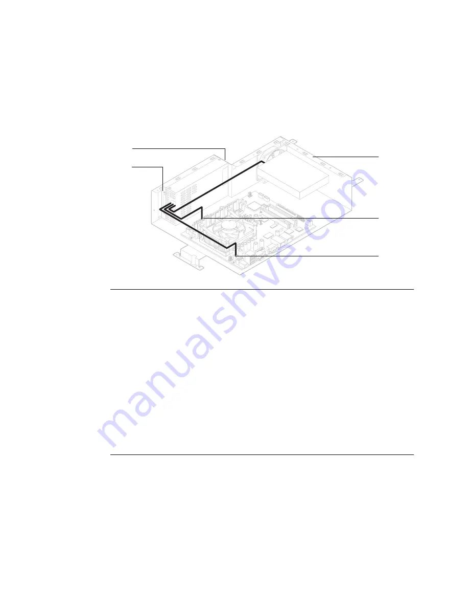
Disconnect the power cables:

• Power cable from motherboard connector J18 

• SATA power cable to HDD

• Power cable to motherboard connector J11

3.

Note the zip ties and how the cables are draped in the pan, and then carefully cut the 
four zip ties that are attached to the pan.

4.

Disconnect the power supply from the pan and back panel (two pan screws and three 
external screws). Lift out the power supply.

You may need to remove the DIMM to access the bottom pan screw.

T

O


REPLACE


THE


POWER


SUPPLY

1.

Insert the power supply into the pan and install the two pan screws and three external 
screws.

2.

Use zip ties to drape the cables and secure them to the pan. 

3.

Connect power cables to the HDD and motherboard J11 and J18 (see figure above).

4.

Reassemble the unit and verify functionality (see page 34).

Pan screw (1 of 2)

Pan

J11

J18

HDD

Po

wer supply

External screws (3)

[not shown]

Содержание Fiery X3eTY 50_45C-KM

Страница 1: ...Fiery X3eTY 50_45C KM A guide for service technicians EFI Part Number 45062331 14 May 2007 Service Guide ...

Страница 2: ...ect to change without notice and does not represent a commitment on the part of EFI The documentation is further covered by Legal Notices distributed with this product which can be found on the User Documentation CD The documentation may be provided in conjunction with EFI Software Software and any other EFI product described in the documentation The Software is furnished under license and may onl...

Страница 3: ...rvice 34 Printing Fiery X3eTY pages 35 Verifying connection to the network 37 System considerations regarding connection to the network 38 System software 39 System software installation reminders 39 Installing system software over the network port 39 Installing system software using a USB flash drive 43 Specifications 47 Hardware features 47 Networking and connectivity 47 Safety and emissions com...

Страница 4: ......

Страница 5: ...ftware already installed Use the procedures in this guide to inspect remove reseat or replace major hardware components and to reinstall system software Replacement parts for the Fiery X3eTY are available from your authorized service support center You must reinstall system software if you replace the hard disk drive HDD or receive a more recent version of the system software You may also reinstal...

Страница 6: ...l components of the print engine Static is always a concern when servicing electronic devices It is highly unlikely that the area around the print engine is static free Carpeting leather soled shoes synthetic clothing fibers silks and plastics may generate a static charge of more than 10 000 volts Static discharge is capable of destroying the circuits etched in silicon microchips or dramatically s...

Страница 7: ...ced with incorrect type Replace the battery only with the same type recommended by the manufacturer Dispose of used batteries according to the manufacturer s instructions ATTENTION Il y a danger d explosion en cas de remplacement avec le mauvais type de batterie Remplacer uniquement avec une batterie du même type recommandé par le constructeur Les batteries usagées doivent être jetées conformément...

Страница 8: ... Gebäude ein Kurzschluss bzw Überstromschutz installiert ist Stellen Sie sicher dass eine Sicherung oder ein Unterbrecher von nicht mehr als 240 V Wechselstrom 10 A bzw in den USA 120 V Wechselstrom 15 A an den Phasenleitern allen stromführenden Leitern verwendet wird ADVERTENCIA Este producto depende de la instalación del edificio en lo relativo a la protección frente a cortocircuitos sobretensió...

Страница 9: ...mation see Figure H on page 12 Key 1 Lid 2 CPU cooling assembly a Clamp b CPU fan and heatsink 3 Interface board 4 DIMM 5 Battery 6 Fiery X3eTY motherboard 7 Fiery X3eTY power supply 8 Enclosed fan 9 HDD cable 10 HDD 11 DIAG board 12 DIAG board cable 13 Pan 14 Connector panel see page 7 15 Extender card 16 Rail 17 Soft power button assembly ...

Страница 10: ... power off the Fiery X3eTY completely Always shut down the Fiery X3eTY properly before you unplug the AC power cable Unplug the AC power cable from the wall outlet before you disconnect other cables connected to the Fiery X3eTY Cable disconnections require a complete power off Power up In general always make sure that the Fiery X3eTY is warmed up before you turn on the copier This is especially im...

Страница 11: ...ystem shuts down the Fiery X3eTY properly so that you can safely power off the Fiery X3eTY Reboot System resets both the Fiery X3eTY and the underlying operating system and then reboots the Fiery X3eTY Choose Shut Down System when you are ready to inspect and or service the Fiery X3eTY according to the following procedure ON 1 2 ON 1 2 Service switches Interface connector for image transmission CO...

Страница 12: ... the Utility Counter key on the print engine 2 Touch Controller Details 3 At the Idle screen press the Menu button on the control panel LCD 4 Use the arrow buttons on the LCD to scroll and choose Shut Down from the menu FIGURE D Menu options 2 of 3 screens 5 At the next menu choose Shut Down System 6 Wait a few minutes for the green LED on the Soft power button to turn off Print Pages USB Media Se...

Страница 13: ...ct the AC power cord from the Fiery X3eTY Power off and unplug the print engine before you remove the Fiery X3eTY from the print engine FIGURE E Fiery X3eTY installed in the print engine Print engine back COPIER port for a LAN cross over cable Fiery X3eTY Print engine right side Interface connector for image transmission cable AC power cord connector and securing clamp ...

Страница 14: ... port cable to the LAN and the print engine cables interface cable and the COPIER port cable If the COPIER port cable is not attached to the print engine see page 38 3 Disconnect the power cable from the Fiery X3eTY 4 Remove the four screws that attach the Fiery X3eTY to the print engine 5 Unhook and remove the Fiery X3eTY from the print engine FIGURE F Accessing the Fiery X3eTY Interface connecto...

Страница 15: ... to the pan see Figure G 7 Lift the lid just enough to reach the HDD SATA power cable 4 wire ribbon cable CAUTION Do not stretch cut or pinch the HDD cables with the lid 8 Disconnect the SATA power cable from the HDD 9 Disconnect the SATA data cable from the HDD 10 Remove the lid with the HDD attached Set the lid and screws aside FIGURE G Lifting the lid off the Fiery X3eTY pan The Fiery X3eTY is ...

Страница 16: ...y socket F4 5 CPU cooling assembly to FAN1 6 PCI1 for interface board extender card 7 LAN port RJ 45 for network cable 8 USB Type A ports 3 9 Enclosed fan cable to motherboard FAN3 1 2 3a 4 5 7 8 9 10 6 12 HDD 13 11a 11b 11c 13 DIAG board ribbon cable from DIAG board J1 to motherboard J2 14 CMOS 3 pin jumper area JP1 15 RJ 45 for cross over LAN cable to print engine or to PC for system software in...

Страница 17: ...mpanies the print engine Motherboard silk screened label Component or cable DIMM1 DIMM2 Socket for upgrade option Socket for standard DIMM U15 PLCC32 socket for BIOS chip SATA1 HDD cable from HDD SATA data connector FAN3 Enclosed fan with attached cable NOTE Airflow is out on CPU no label visible CPU cooling assembly FAN1 CPU cooling assembly fan with attached cable PCI1 Extender card for interfac...

Страница 18: ...you can properly arrange the cabling later with new tie wraps Tie wraps are included in the motherboard spare kit Power supply cable at motherboard J11 Power supply cable at motherboard J18 HDD cable at motherboard SATA1 Enclosed fan cable at motherboard FAN3 DIAG board ribbon cable at motherboard J2 Soft power button cables two at motherboard connector labeled Front Panel Four wires left to right...

Страница 19: ...OS chip For the proper procedures see Removing and replacing components on page 17 Remove the battery from the new motherboard see page 22 Set aside the battery so that you can replace it later Locate the jumper that is installed on the 3 pin jumper area JP1 on the motherboard JP1 is located between motherboard connectors PCI2 and PRI IDE Remove the jumper from the default position on JP1 and inst...

Страница 20: ...s are labeled SW LED and SW SW LED wires are red and black SW wires are red and yellow DIAG board ribbon cable at J2 Enclosed fan cable at FAN3 HDD cable at SATA1 Power supply cables at J11 and J18 5 Install the extender card with rail attached into motherboard connector PCI1 Align the rail onto the pan and install the two screws you removed earlier 6 Install the interface board see page 19 7 Reas...

Страница 21: ...hooting see page 49 The following sections describe how to remove and install removable replaceable parts on the Fiery X3eTY Interface board DIMMs BIOS chip Battery CPU and CPU cooling assembly DIAG board Enclosed fan Soft power assembly Power supply Hard disk drive HDD For information about replacing other components see the documentation that accompanies the print engine CAUTION Make sure that y...

Страница 22: ...which is connected directly to the Fiery X3eTY motherboard see Figure I below and Figure B on page 5 FIGURE I Interface board connections Use the following procedures to remove or replace the interface board CAUTION Make sure that you wear an ESD grounding wrist strap and follow standard ESD precautions while handling Fiery X3eTY components Rail Interface board connected to extender card Extender ...

Страница 23: ... to remove the rail or the two jackscrews 3 Disconnect the interface board from the bottom slot of the extender card Lift out the interface board from the pan Set the board and the screws aside TO REPLACE THE INTERFACE BOARD 1 Insert the interface board into the bottom slot of the extender card 2 Attach the interface board to the pan with the two screws you removed earlier 3 Reassemble the unit an...

Страница 24: ...outward on the lever on each side of the DIMM see Figure J FIGURE J Releasing a DIMM 2 Slide the DIMM straight out of the socket to avoid damaging the DIMM or the socket and set the DIMM aside 3 To install a DIMM insert it straight into the socket Push the DIMM into the socket until the levers snap into place The DIMM fits the socket only one way The notch on the bottom of the DIMM should line up ...

Страница 25: ... chip use the following procedure TO INSTALL THE BIOS CHIP 1 Locate the motherboard PLCC32 socket U15 2 If a BIOS chip is already installed in the socket remove it using a PROM extractor Make sure not to put stress on surrounding components or connectors 3 Place the required BIOS chip on the socket so that the notch in the chip is aligned with the notch in the socket FIGURE K BIOS chip in socket 4...

Страница 26: ... leverandøren VAROITUS Paristo voi räjähtää los se on virheellisesti asennettu Vaihda paristo ainoastaan laitevalmistajan suosittelemaan tyyppiin Hävitä Käytetty paristo valmistajan ohjeiden mukaisesti ADVARSEL Eksplosjonsfare ved feilaktig skifte av batteri Benytt samme batteritype eller en tilsvarende type anbefalt av apparatfabrikanten Brukte batterier kasseres i henhold til fabrikantens instru...

Страница 27: ...Always replace both the CPU and the cooling assembly when you decide to replace either NOTE You should not need to remove the fan from the heatsink A replacement cooling assembly ships with the fan already attached This procedure assumes you will use the existing clamp even though a replacement cooling assembly ships with a clamp FIGURE L CPU cooling assembly Follow standard ESD precautions while ...

Страница 28: ...and pull the clamp crossbar away from the bracket hooks FIGURE M CPU cooling assembly orientation 5 Lift off the fan heatsink and set it aside If the clamp is not interfering let the clamp s other two hooks close to the FAN1 side remain inserted in the bracket slots Not removing the clamp may better protect the tall capacitors from inadvertent damage Use caution when lifting off the fan heatsink T...

Страница 29: ...U into the socket Make sure that you align the arrow indicating pin 1 on the CPU with pin 1 in the CPU socket see Figure N 3 Lower the CPU socket lever beneath the retention post to lock the CPU in place 4 Position the fan heatsink over the CPU so that the fan cable is near the FAN1 connector NOTE The cooling assembly includes a square piece of foil over the thermal compound on the bottom of the h...

Страница 30: ... down on the clamp levers and guide the clamp crossbar toward the bracket hooks 7 Connect the CPU fan cable to motherboard connector FAN1 If you are installing a new CPU secure the slack in the fan cable using a tie wrap if necessary The tie wrap prevents the fan cable from interfering with the CPU fan Make sure that the cable connector is securely connected to connector FAN1 on the motherboard 8 ...

Страница 31: ... Do not pull the wires of the cable Pull the cable out by its connector 3 Remove the four screws that secure the DIAG board to the pan 4 As you remove the DIAG board carefully slide the ribbon cable through the space between the extender card and the pan Set the screws aside so you can replace them later 5 Remove the ribbon cable from connector J1 on the DIAG board TO REPLACE THE DIAG BOARD CAUTIO...

Страница 32: ... the side that the air flows towards 3 Remove the rivets that secure the fan to the back of the pan remove the fan Tip Use a small screwdriver or similar tool less than 4 4 mm in diameter Insert the tool into each access hole find the center of the rivet and push the rivet out 4 Secure the new fan inside the pan using the rivets just removed Make sure that the new fan is in the same orientation as...

Страница 33: ...the Soft power cables one pair at a time through the cutout TO REPLACE THE SOFT POWER BUTTON ASSEMBLY 1 Carefully insert the Soft power button cables through the cutout in the chassis Insert the cables one pair at a time through the cutout 2 Push the button assembly firmly into the cutout until the assembly is locked in place Make sure that the beveled sides of the button casing are completely sec...

Страница 34: ... Note the zip ties and how the cables are draped in the pan and then carefully cut the four zip ties that are attached to the pan 4 Disconnect the power supply from the pan and back panel two pan screws and three external screws Lift out the power supply You may need to remove the DIMM to access the bottom pan screw TO REPLACE THE POWER SUPPLY 1 Insert the power supply into the pan and install the...

Страница 35: ...ls what fonts are resident on the Fiery X3eTY Along with the fonts that are provided on the System Software CD the customer may have installed additional fonts that will be deleted when system software is installed For information about installing system software see page 39 Proper handling Handle the HDD with care Use proper ESD practices when grounding yourself and the Fiery X3eTY Keep magnets a...

Страница 36: ...wer cable and the HDD cable from the HDD NOTE Do not stretch the cables as you lift the lid 3 Remove the four HDD screws from the outside of the pan lid Lift out the HDD Hold the HDD as you remove the last screw Set the screws aside so that you can replace them later 4 Place the HDD in an antistatic bag Do not touch the drive with magnetic objects such as a magnetic screwdrivers Do not place items...

Страница 37: ...ts see Proper handling on page 31 2 Secure the HDD to the pan lid using the four screws you removed earlier see page 5 3 Firmly connect the HDD cable and the SATA power cable to the HDD NOTE DO NOT USE THE 4 PIN POWER CABLE 4 Reassemble the unit and verify functionality see page 34 NOTE If you replaced the HDD you must install system software according to the procedure in System software on page 3...

Страница 38: ...ngine cables COPIER port cable and interface cable 3 If you installed a new HDD install system software according to the procedure in System software on page 39 NOTE A spare HDD is shipped without system software 4 Make sure that the service switches are set for normal operation both away from the DIAG LEDs If necessary shut down the Fiery X3eTY and flip their position you do not have to unplug th...

Страница 39: ... effect from the current Setup After you have finished running Setup print a Configuration page to confirm your settings If the Fiery X3eTY is rebooting allow the Fiery X3eTY to reboot and return to Idle before printing a Configuration page Before you perform any service procedure print the Fiery X3eTY Configuration page if possible so that you are prepared to return the settings to their former c...

Страница 40: ...TP Log 6 Examine the Test Page If the Test Page prints you know the Fiery X3eTY print engine is functional and that the connection between the Fiery X3eTY and the copier is operating properly When you examine the PS Test Page consider the following All swatches should be visible even though they may be very faint in the lowest ranges Swatches should show uniform gradation as the tone lightens Poor...

Страница 41: ...100BaseTX Category 5 or higher 4 pair 8 wire short length For 1000BaseT Category 5e or higher 4 pair 8 wire short length NOTE If the print engine is 230V use a shielded network cable The network cable connects to the LAN port on the connector panel of the Fiery X3eTY see Figure P FIGURE P Network connectors and service switches LAN port for 10 100 1000BaseT twisted pair Ethernet Service switches U...

Страница 42: ...ew test documents from a networked computer that will use the Fiery X3eTY For more information see Configuration and Setup on the User Documentation CD System considerations regarding connection to the network When the cross over LAN cable is used as described in this service guide to connect the print engine to the COPIER port on the Fiery X3eTY be aware of the following The following network fun...

Страница 43: ... format the HDD and again after you complete the system software installation Any fonts not listed after installation must be reinstalled For more information see Utilities on the User Documentation CD Language Screens for installing system software are always displayed in English even if the print engine is configured for another language Compatibility The latest user software must be installed o...

Страница 44: ...staller vbs icon Do not double click Installer exe NOTE If you double click Installer exe instead of Installer vbs you may get the following error during the installing of CD 2 Windows Wrong Volume The wrong volume is in the drive Please insert volume Fiery into drive E Cancel Try Again Continue In this case you must power off the Fiery X3eTY and perform the system software installation procedure ...

Страница 45: ...t CD2 and click Retry The progress is slow at first For most computers expect to wait approximately 25 minutes to complete do not cancel If you do click Cancel Click Finish power off the Fiery X3eTY using the Soft power button wait 10 seconds and then repeat this procedure from the beginning If the installation terminates abnormally you may need to reboot the PC also To avoid confusion ignore the ...

Страница 46: ...age selection screen 22 At the Setup screen select Run Setup and press OK Reenter the customer s settings from the Configuration page that you printed earlier Enter settings for Server Network and Printer Setup in that order Ignore the settings not included on the Configuration page if it is more appropriate for the site administrator to set them For more information see Configuration and Setup on...

Страница 47: ...86 compatible microprocessor CD ROM drive built in or attached Support for USB 2 0 USB 1 1 may work but it will be very slow 1 5GB minimum memory capacity PS 2 keyboard mouse input is not accepted by the software on the USB Flash Tool CD System Software CDs 2 USB Flash Tool CD To install system software using a USB 2 0 flash drive you must use a flash drive that has been prepared already The proce...

Страница 48: ... If booting from the CD still fails try another PC It could be that your PC is not compatible with the boot program on the USB Flash Tool CD 3 Follow the USB Flash Tool screen prompts To respond to a prompt use only the keyboard Do not use the mouse The following descriptions are based on the USB Flash Tool CD v2 2 If the USB Flash Tool CD is revised some of these descriptions may not apply Additi...

Страница 49: ...nd the next prompt appears 5 USB flash device is ready for installation The device can be safely removed OK Disconnect the flash drive from the USB A port Press Enter 6 Do you want to program more USB flash drives Yes No Select No unless you are preparing more than one USB flash drive 7 System will shutdown Yes No Select Yes 8 Processing complete Please remove CD Rebooting Remove the system softwa...

Страница 50: ...fter the Fiery X3eTY powers off and the DIAG LEDs go out wait at least 30 seconds and then remove the USB flash drive from the Fiery X3eTY 8 Press the Soft power button for 2 seconds to restart the Fiery X3eTY 9 Select a language to view the Language Selection screen press the Utility Counter key and then touch Controller Details when it appears on the Control Panel LCD 10 If you selected English ...

Страница 51: ...ling system software from CD 3V manganese dioxide lithium coin cell battery Panasonic CR2032 or equivalent Dedicated power supply Soft power button green LED Networking and connectivity The Fiery X3eTY has the following networking features Supports AppleTalk TCP IP and IPX protocols simultaneously RJ 45 Ethernet LAN port for twisted pair 10BaseT 100BaseTX 1000BaseT network connection NOTE The late...

Страница 52: ... EMC approvals EN60950 1 TUV GS UL 60950 1 CAN CSA C22 2 No 60950 1 cULus Listed Accessory IEC60950 1 NEMKO FCC Class A ICES003 Class A EN55022 Class B EN55024 TUV EMC AS NZS CISPR Class B AS NZS 4252 1 THE FIERY X3eTY ALSO KNOWN AS FIERY X3eTY2 IMAGE CONTROLLER MODEL IC 409 ARE IDENTICAL AND SHALL BE USED WITH UL LISTED ITE MODEL C451 550 650 ...

Страница 53: ...o the customer site With a phone call you can find out if the problem is a simple operating failure or a failure caused by a network or configuration change You can ask the customer to check for loose cables on the back of the print engine and loose connections at a power strip or outlet Check for obvious causes of problems Check network connections Preliminary on site checkout on page 52 takes yo...

Страница 54: ...ices Print engine Fiery X3eTY assembly 5VDC CPU LAN interface PCI memory controller Print engine Print Memory Networked computers PC RTC PCI ISA USB interface Battery Image transmit interface PCI bus SATA HDD Power supply Control Panel interface PC Soft Power button Cross over LAN interface ...

Страница 55: ...of printers If the answer to any of these questions is yes refer the customer to Configuration and Setup on the User Documentation CD or Command WorkStation Help If the customer has followed the suggested corrective actions and has failed to solve the problem be prepared to make a service call Keep a log of the failures the customer has observed 3 Has the customer made any network changes If netwo...

Страница 56: ...roperly connected to the print engine If all the connectors are in place and the problem still exists when the print engine is powered on proceed to the next phase of troubleshooting NOTE For convenience the procedure To check internal connections on page 13 is repeated here under Troubleshooting See other documentation for guidelines when disassembling checking and reassembling the print engine T...

Страница 57: ...s 3 9 Enclosed fan cable to motherboard FAN3 1 2 3a 4 5 7 8 9 10 6 12 HDD 13 11a 11b 11c 13 DIAG board ribbon cable from DIAG board J1 to motherboard J2 14 CMOS 3 pin jumper area JP1 15 RJ 45 for cross over LAN cable to print engine or to PC for system software installation NOT SHOWN Extender card Interface board Service switches Default Position JP1 Reset Position JP1 10 Soft power button cables ...

Страница 58: ...he print engine Motherboard silk screened label Component or cable DIMM1 DIMM2 Socket for upgrade option Socket for standard DIMM U15 PLCC32 socket for BIOS chip SATA1 HDD cable from HDD SATA data connector FAN3 Enclosed fan with attached cable NOTE Airflow is out on CPU no label visible CPU cooling assembly FAN1 CPU cooling assembly fan with attached cable PCI1 Extender card for Interface board J...

Страница 59: ...d then shuts down One of the following Faulty connection betweenFiery X3eTY and print engine Faulty power supply Faulty motherboard Faulty CPU Faulty interface board 1 Check and reseat the interface cable between the Fiery X3eTY and the print engine 2 Replace the interface cable 3 Listen for the power supply fan and feel for air near where the power supply is located If you do not feel air from th...

Страница 60: ... to remove any oxidation on the connectors 8 If two DIMMs are installed determine if a DIMM is at fault Remove the DIMM currently installed in socket DIMM1 and reboot the system Reboot again with the other DIMM installed in DIMM2 If the problem is solved by one of the DIMMs replace the other DIMM If the problem persists for both DIMMs proceed to the next step 9 Clear the CMOS and power up settings...

Страница 61: ...MM is installed in the correct slot see page 20 2 Check for missing DIMMs and reseat the DIMMs to remove any oxidation on the connectors 3 If two DIMMs are installed determine if a DIMM is at fault Remove the DIMM currently installed in socket DIMM1 and reboot the system Reboot again with the other DIMM installed in DIMM2 If the problem is solved by one of the DIMMs replace the other DIMM If the p...

Страница 62: ...he flash drive may be improperly seated Power off the Fiery X3eTY reseat the flash drive power on and then allow the installation to resume 4 Retry the installation using a different USB flash drive 5 Reseat the cables to the HDD 6 Replace the HDD cable 7 Replace the HDD 8 Clear the CMOS and power up settings see page 69 9 Replace the motherboard 10 Replace the CPU USB flash drive method During in...

Страница 63: ...he installer screen and then retry the installation 2 Make sure that you are using the COPIER port not the LAN port 3 Make sure that you are using a cross over cable The COPIER cable is a cross over type and may be used for system software installation If the cable appears damaged replace it 4 Clear the CMOS and power up settings see page 69 5 Replace the motherboard Network port method Installati...

Страница 64: ...he COPIER port The COPIER port is reserved for the print engine interface and for installing system software from a PC Faulty network cable or connection Faulty network Faulty Ethernet interface on the motherboard 1 Make sure that the network cable is the correct type and connected to the designated LAN port on the Fiery X3eTY connector panel 2 Check the cable connection to the network 3 Replace t...

Страница 65: ... sure that the cable is the correct type 3 If the network cable is the correct type and is properly connected to the Fiery X3eTY connect a new network cable to the Fiery X3eTY 4 Request that the network administrator check other devices on the network If other devices are not functioning there could be a problem with the network 5 If the rest of the network is functioning properly and the problem ...

Страница 66: ...he power button for a few seconds to turn on the Fiery X3eTY 2 Power off on the print engine 3 Make sure that the Network Scanning option is available from the print engine control panel 4 Check again that the print engine interface cable is present and properly connected to the Fiery X3eTY and the print engine 5 Check again that the print engine interface board is present and properly connected t...

Страница 67: ... the system Reboot again with the other DIMM installed in DIMM2 If the problem is solved by one of the DIMMs replace the other DIMM If the problem persists for both DIMMs proceed to the next step 4 Clear the CMOS and power up settings see page 69 5 Replace the motherboard A print job stalls or stops after one or a few pages PostScript or application error 1 Cancel the Fiery X3eTY print job 2 If th...

Страница 68: ...librator window Restore Device restores the Fiery X3eTY calibration information to factory defaults If restoring default calibration does not solve the problem you may need to service the print engine 2 If restoring default calibration fixes the color quality the custom calibration may have been the cause of the problem Request that the site administrator recalibrate the Fiery X3eTY For details se...

Страница 69: ...on and then click Restore Device in the Calibrator window Restore Device restores the Fiery X3eTY calibration information to factory defaults If restoring default calibration does not solve the problem you may need to service the print engine 2 If restoring default calibration fixes the color quality the custom calibration may have been the cause of the problem Request that the site administrator ...

Страница 70: ...uration page from the print engine control panel but cannot print a job from a computer on the network request that the network administrator do the following Check all components of the network including cables connectors terminators network adapter boards and network drivers Activate the network and use it to communicate with other printers Confirm that the applicable network settings in Setup s...

Страница 71: ...ng errors caused by missing or incorrectly installed printer description files Printing to the Fiery X3eTY If the customer can print the Fiery X3eTY Test Page but cannot print a job from a computer on the network you may have to make a service call However first Make sure that the site administrator has done the following Checked all components of the network including cables connectors terminator...

Страница 72: ... input trays Can you print a Test Page from the printer driver If you cannot the print engine may be out of order You may need to service the print engine Enclosed fan not present or not functioning Verify that the enclosed fans are present oriented correctly and functioning see page 28 TABLE C Other printing problems Problem Action An image is printed on the reverse side of the paper Reload the p...

Страница 73: ...the battery so that you can replace it later 4 Locate the jumper that is installed on the 3 pin jumper area JP1 on the motherboard JP1 is located between motherboard connectors PCI2 and PRI IDE 5 Remove the jumper from the default position on JP1 and install it in reset position 6 Wait one full minute 7 Remove the jumper from the reset position on JP1 and install it back in default position 8 Rein...

Страница 74: ......

Страница 75: ...64 65 66 DIMMs configurations 20 removal and replacement 20 E EMI approvals 48 errors 60 61 62 63 64 65 66 ESD electrostatic discharge safety precautions 2 14 17 exploded view 5 F fan CPU 23 enclosed 28 34 H hard disk drive proper handling 31 removal 33 system software 31 heatsink CPU 23 I interface board 18 IP address 2 L LAN local area network 2 N networks connecting to 37 67 supported 47 O on b...

Страница 76: ......

Отзывы: