


Schmid & Wezel
D-75433 Maulbronn
Seite / Page
Ausführung / Execution
05.2004
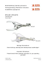
27
1
Cutter body
003 008 536
28
4
Hexagon socket head screw
002 000 275
30
2
Cover (right)
003 008 741
31
2
Cover (left)
003 008 742
32
12
Hex. head bolt
001 325 921
33
1
Bracket
003 008 526
34
2
Spring washer
001 317 003
35
2
Hex. head bolt
001 325 908
36
2
Blade complete (each with 1 piece 37 +
40)
007 008 542
007 009 046
37
4
Slide bearing
001 346 002
38
1
Stud bolt (with 39)
007 008 540
39
1
Grease nipple
001 305 802
40
2
Slide bearing
001 346 003
41
1
Washer with external tab
001 311 515
42
1
Hex. nut
001 304 630
43
2
Fork complete (each with 1 piece 37)
007 008 543
44
1
Bolt
003 008 541
45
1
Yoke
003 008 539
46
2
Bolt
003 005 083
47
3
Taper sleeve
001 307 009
Flange assy. (48 - 55)
008 005 277
48
1
Flange
003 005 056
49
1
Pressure spring
003 003 932
50
1
Valve pin
003 005 063
51
1
O-ring
001 312 620
52
1
O-ring
001 312 627
53
1
Valve insert
003 005 055
54
1
O-ring
001 312 636
55
1
Snap ring
001 312 313
56
2
Flat-head socket head cap screw
001 326 515
57
4
Male fitting
001 610 601
58
2
Flexible Rilsan hose
001 610 658
59
3
Cable tie
001 371 916
60
1
Coupling socket (with 61-62)
001 606 590
61
1
O-ring (inner)
001 312 649
61A
1
Back-up ring (inner)
001 317 801
62
1
O-ring (outer)
001 312 670
63
1
Elbow male fitting
001 606 597
64
1
Straight male fitting with shaft
001 606 598
65
1
Plug connector
001 606 591
Wear set for cutter (2 - 4, 8, 10, 12, 16,
18, 37, 40, 49,
007 899 488
Hose unit assy. (70 - 84)
008 005 181
Flow
Hydraulic hose ass'y. (70 - 71)
001 606 577
70
1
Hydraulic hose
001 606 582
71
1
Plug connector
001 606 578
Return flow
Hydraulic hose ass'y. (72 - 75)
001 606 579
72
1
Hydraulic hose
001 606 583
73
1
Coupling socket (74-75)
001 606 580


