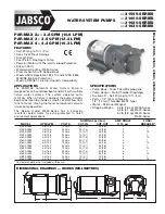
Ultima Bilge - Automatic Bilge Pump
Caution: Please read and follow all instruc-
tions before installing and using this prod-
uct.
Always disconnect power sources dur-
ing installation, servicing or maintenance
of this product. The Ultima Bilge pump
has been carefully designed to exhaust
standing water only. These pumps are not
intended for damage control. Bilge pump
capacities may not be sufficient to prevent
flooding from rapid accumulation of water
due to storms, rough weather and/or rapid
leaks created by hull damages and/or un-
safe navigational conditions.
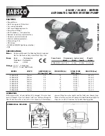
About the Ultima Bilge Pump
The Ultima Bilge pump is a state of the art
automatic bilge pump that uses advanced
electronic sensing technology to detect
the presence of water in the bilge area of
a boat and consequently discharge of that
water. It is built upon the proven UltimaS-
witch technology which uses micro electri-
cal fields to detect the presence of water.
The Ultima Bilge pump is a sealed, sub-
mersible pump and electronic float switch
that allows for a simple installation for the
end user.
Warnings:
To eliminate personal injury or damage to
property during installation, servicing and
maintenance, make sure to disconnect
electrical power.This pump was designed
to remove standing bilge water only and
should not be used to pump petroleum
products such as gasoline, oil, or flam-
mable liquids.
Make sure to use the appropriate fuse size
recommended by your pump model. Using
the wrong fuse can lead to personal injury,
property damage and fire hazard.
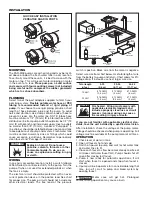
Installing the Ultima Bilge Pump:
Caution:
When installing the Ultima Bilge
Pump, make sure that pump is clear of all
obstacles, especially near the detector
area. If detectors are blocked, the pump
will remain continuously on!
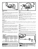
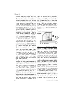
1) Place a 3/4” thick block of marine ply-
wood as a mounting block for your
pump base. Mounting block should be
large enough to cover the strainer area.
Use a waterproof adhesive to attach
mounting block to the hull of the vessel.
Make sure that mounting block is as flat
as possible. Place pump in the lowest
area of the bilge. Also, make sure dis-
charge nozzle is level.
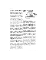
2) Remove the pump from the strainer by
depressing the two side tabs and pull-
ing the strainer from pump body. Use
the strainer to mark three mounting
holes. In order to avoid drilling through
the hull of the vessel, set your drill to the
appropriate depth for the pilot holes.
Drill your pilot hole.
3) Drive three #8 x 5/8” (not supplied)
Stainless screws into the strainer holes
to mount the strainer. Do not over tight-
en.
4) After the strainer is mounted down,
place pump body onto strainer making
sure that the side tabs lock onto pump
body.
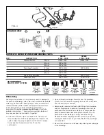
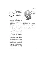
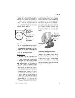
For ¾” discharge models attach your hose
over the Duraport. Use Stainless steel
hose clamps to secure the hose. If install-
ing the optional check valve, make sure to
install the check valve into the Duraport
before installing the hose. For 1 1/8”
models attach your hose over threaded
port [1 1/8” or 1¼”]. Use Stainless Steel
hose clamps to secure the hose to the
ports. If installing the optional check valve,
7
Original instructions
> English
Содержание 268 Center Console
Страница 1: ...268CC 268 Center Console OWNER ASSISTANCE MANUAL Revised 2014...
Страница 32: ...31 Appendix 268CC...
Страница 33: ...34...
Страница 34: ...35 Hydraulic Steering System...
Страница 35: ...36...
Страница 36: ...37...
Страница 37: ...38...
Страница 38: ...39...
Страница 39: ...40...
Страница 40: ...41...
Страница 74: ...ENCO ARINE NC UNICIPAL OURT s 3TUART LORIDA s FAX s WWW LENCOMARINE COM DON T WORRY we ve got your back 8 07...
Страница 112: ......
Страница 129: ......
Страница 131: ...50890 Waste Pump Pompe d eaux us es F kalienpumpe Pompa di scarico Afvoerpomp T mningspump Bomba para desechos...
Страница 146: ...8 Rotation of Ports 1 2 3 4 5 6 7 1 Rotation of Pump Head 2 3 4 5...
Страница 186: ...38 A B 50 mm C 20 mm...

