10
en
circuit
shock cleanIng
Oil-filled shocks will require regular maintenance due to the oil
breaking down or getting dirty. This maintenance should be performed
after about every 3 to 5 hours of use, depending on the conditions that
the vehicle is used in.
• Remove the shock from the vehicle.
• Remove the cap from the shock body and dispose of fluid.
• Disassemble the shock. Clean thoroughly with DYN5505. Dry parts
before assembly.
• Re-assemble the shock and refill the shock body with silicone fluid
(30 weight recommended).
• Slowly move the shaft and piston up and down to remove
air bubbles.
• Move the piston to the midway point of the body and
install the cap.
• Wipe off any overflowing fluid.
• When properly filled, the piston should rebound about
3/8 in (9.5mm) after being pushed in fully.
• Re-install the shock on the vehicle.
ride height adjustment
Ride height is an adjustment that affects the way the vehicle
jumps, turns and goes over bumps. Drop one end of the vehicle
from approximately 6 inches (152 mm) in height onto a flat
surface. When dropping the front of the vehicle, after the vehicle
settles, make sure the front arms are equal and parallel to the
flat surface. Do the same with the rear to make sure both arms
are parallel with the flat surface.
Lowering the front ride height increases steering, but decreases
traction. Lowering the rear ride height increases traction, but
decreases steering.
rear shock
front shock
Front Shock
ECX1043
ECX1037
ECX1037
ECX1041
ECX1037
ECX1043
Rear Shock
ECX1036
ECX1038
ECX1038
ECX1043
ECX1037
ECX1037
ECX1038
ECX1042
ECX1040
ECX1057
ECX1037
ECX1043
ECX1038
ECX1039
ECX1036
ECX1038
ECX1038
ECX1037
ECX1057
Part #
Description
ECX1036
Shock Body Set
ECX1037
Shock Caps, Pistons
ECX1038
Shock Parts Set
ECX1039
Front Shock Shaft (2)
ECX1040
Rear Shock Shaft (2)
ECX1041
Front Shock Springs (2)
ECX1042
Rear Shock Springs (2)
ECX1043
Shock O-Ring Set
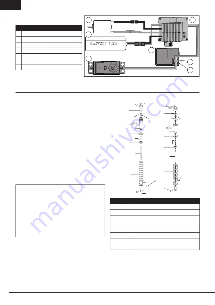
electrIcal layout
Part #
Description
A DYN1171
Motor
B DYN1050EC
Battery 7.2V
C DYN3900
Steering Servo
D ECX9011
Receiver
E DYN4925WP Electronic Speed Control (ESC)
F
Channel 1
G
Channel 2
For correct operation, Channels 1 and 2 must be used
as shown in the wiring diagram. The motor can be
disconnected from the ESC at the connectors in the
wiring.
EC3
EC3
a
B
c
d
f
g
e


