30
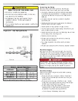
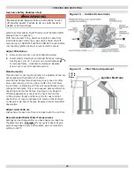
SAFETY RELIEF VALVE [ Figure 2, Page 7 ]
Safety relief valve is required on your boiler. Water expands
as it is heated. If there is no place for water to expand
into, water pressure will build up inside boiler and system.
Should this happen, safety relief valve will automatically
open at predetermined pressure. This will relieve the strain
on boiler and system. Run pipe from relief valve outlet
(pipe must be same size as outlet and open end must not
be threaded) to open drain, tub or sink, or other suitable
drainage point not subject to freezing. Failure to do so may
cause water damage or injury should safety relief valve
release.
EXPANSION TANK
Expanding water
fl
ows into expansion tank. Tank should
be correct size. Tank is
fi
lled with air. As water expands it
compresses air in the tank to form air pressure cushion.
This “spring-like” cushion serves to maintain correct
operating water pressure regardless of water temperature.
This assures “full measure” of water, even in highest
radiation unit of system. It also prevents blowing off of
safety relief valve. Air in tank in beginning (with system
fi
lled with cold water) is suf
fi
cient for proper operation.
Tank also serves as trap for excess air in system. Air
would cause gurgling in pipes and in ef
fi
cient circulation in
radiators if left in system.
It is possible for tank to become “waterlogged” (
fi
lled
with water). It can also become over
fi
lled with air. This
can happen after
fi
lling system with new water. Fittings
provided on tank and in line to tank are for bleeding off
excess water or air.
When installing this tank, it is important:
1.
Tank be higher than boiler top.
2.
Pipe to tank continuously rises up to tank (so air
can “bubble” up to it).
DIAPHRAGM TYPE EXPANSION TANK
Diaphragm type expansion tank takes place of conventional
expansion tank. Carefully read instructions packed with
your tank assembly.
Tank comes with 10-12 pounds per square inch air charge.
This is the same as pressure produced in system by
automatic
fi
ll valve. When system is
fi
rst
fi
lled, tank will
contain little or no water.
As water is heated its pressure increases. It expands into
tank, compressing air in tank. Compressed air cushion
permits water in system to expand as temperature
changes. Diaphragm type tank can be mounted on air
purger
fi
tting or at any convenient place in supply or return
line.
AIR ELIMINATING FITTING (AIR PURGER)
Air purger is used to remove excess air from system. It
is installed in supply line. It will eliminate air from water
before it reaches radiators and bleed off this air.
MAIN AIR VENT FOR DOWN FLOW SYSTEMS OR
DIAPHRAGM TYPE EXPANSION TANK
Before system is
fi
lled with water, there is air in pipes and
radiation units. Some of it will be trapped as system is
fi
lled . It is possible to eliminate most of this air through
air vent on radiation units. Main air vent will speed and
simplify this. Install on highest point in supply main when
all radiation is below top of boiler.
AUTOMATIC FILL VALVE
For a safe, ef
fi
cient operation, hot water system must be
completely
fi
lled
with water. Adding new water, when
needed can be done manually (by use of hand valve in
water supply line). Requires regular attention to system’s
needs. Automatic
fi
ll valve accomplishes this without
attention. Install in supply line on hot water boilers only.
Valve operates through water pressure differentials. It does
not require electrical connection.
DRAIN VALVE
Manual valve provides means of draining all water from
boiler and system. It is often installed in 3/4” tapping at
bottom of end boiler section. Or it can be installed in tee
where return line enters boiler.
EQUIPMENT & OPTIONAL ACCESSORIES
WATER TEMPERATURE CONTROL
Water temperature limit control in relay is adjustable
and may be set as necessary. It may be set as low as
140°F, or as high as 220°F. This depends on type and
amount of radiation involved and weather conditions.
CIRCULATING PUMP
Every forced hot-water system requires circulating pump.
Separate pump or zone valve is required for each zone,
if you have a two or more zone system. Pump must have
capacity to provide circulation required by your system.
Pump is connected into main just ahead of boiler. It is also
wired to electrical system.
BLOWER (Draft Inducer)
Blower provides means for pulling air through boiler and
exhausting
fl
ue gasses into vent system. Blower shuts
off when burners are not
fi
ring. This keeps heat in house
rather than having it go up chimney.
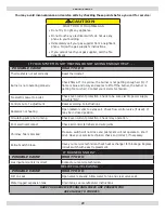
WARNING
Burn
and scald hazard. Safety relief valve could
discharge steam or hot water during operation.
Install discharge piping per these instructions
.
!
Содержание UTICA BOILERS SVB II Series
Страница 4: ...4 DIMENSIONS Model Width A SVB 2 11 SVB 3 14 1 4 SVB 4 17 1 2 SVB 5 20 3 4 SVB 6 24 SVB 7 27 1 4 ...
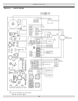
Страница 23: ...23 WIRING DIAGRAMS Figure 12 Control Module Damper is not an option ...
Страница 37: ...Date Service Performed Company Name Tech Initials Company Address Phone ...
Страница 38: ...NOTES ...
Страница 39: ...Date Service Performed Company Name Tech Initials Company Address Phone ...
Страница 40: ...UTICA BOILERS 2201 Dwyer Avenue Utica NY 13501 web site www ecrinternational com ...


