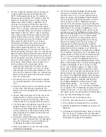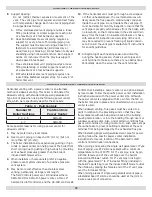
19
CAUTION
WHAT TO DO IF YOU SMELL GAS
• Do not try to light any appliance.
• Do not touch any electrical switch; do not use
any phone in your building.
• Immediately call your gas supplier from a
neighbor’s phone. Follow gas supplier’s
instructions.
• If you cannot reach your gas supplier, call the
fi
re
department.
!
!
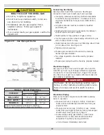
Table 4 - Supply Piping Size
PRESSURE
GAS
NATURAL
PROPANE
MIN. SUPPLY
5" w.c.
11" w.c.
MAX. SUPPLY
13.5" w.c.
13.5" w.c.
MANIFOLD
3.5" w.c.
10" w.c.
Verify minimum pressure while boiler is operating.
Verify maximum prssure when boiler is not operating
Connecting Gas Piping
Gas line enters boiler from right side. Flexible gas
connectors must never breach any boiler openings.
• Use piping materials and joining methods acceptable
to authority having jurisdiction. In absence of such
requirements National Fuel gas Code, ANSI Z223.1/
NFPA 54
• All pipe compound must be resistant to lique
fi
ed
petroleum gas.
• Install ground joint union in gas supply line between
shut-off valve and boiler controls.
• Install sediment trap upstream of gas controls.
• Use two pipe wrenches when making connection to gas
valve to keep it from turning.
• Install manual shut-off valve in vertical pipe about 5 feet
(1.5m) above
fl
oor. See Figure 10 .
• Tighten all joints securely.
• Propane gas connections should only be made by
licensed propane installer.
• Two-stage regulation should be used by propane
installer.
• Propane gas piping should be check by propane installer.
Check Gas Supply
Gas pipe must be correct size for length of run and for
total BTU per hour input of all gas utilization equipment
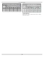
connected to it. See Gas Table 6 & 7, Page 20 for proper
size. Be sure your gas line complies with local codes and
gas company requirements.
DANGER
Fire Hazard. Do not use matches, candles, open
fl
ames, or other methods providing ignition source.
Failure to comply will result in death or serious
injury.
!
Check Gas Piping
Pressure test boiler and gas connection before placing
boiler in operation.
• Pressure test over 1/2 psig (3.5 kPa). Disconnect
boiler and its individual gas shutoff valve from gas
supply system.
• Pressure test at 1/2 psig (3.5 kPa) or less. Isolate
boiler from gas supply system by closing manual gas
shutoff valve. See Figure 5 & 6, Page 9.
• Locate leakage using gas detector, noncorrosive
detection
fl
uid, or other leak detection method
acceptable to authority having jurisdiction.
• Correct leaks immediately and retest.
GAS SUPPLY PIPING
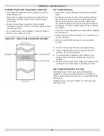
Figure 10 - Gas Piping At Boiler
Содержание UTICA BOILERS SVB II Series
Страница 4: ...4 DIMENSIONS Model Width A SVB 2 11 SVB 3 14 1 4 SVB 4 17 1 2 SVB 5 20 3 4 SVB 6 24 SVB 7 27 1 4 ...
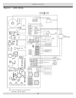
Страница 23: ...23 WIRING DIAGRAMS Figure 12 Control Module Damper is not an option ...
Страница 37: ...Date Service Performed Company Name Tech Initials Company Address Phone ...
Страница 38: ...NOTES ...
Страница 39: ...Date Service Performed Company Name Tech Initials Company Address Phone ...
Страница 40: ...UTICA BOILERS 2201 Dwyer Avenue Utica NY 13501 web site www ecrinternational com ...


