background image

28141 Rev A 10-27-06 

7

Soot behaves as an insulator and impairs good 
heat transfer. Stack temperature will increase, 
and the overall efficiency will decrease. As a 
means of avoiding this problem, it is advisable to 
adjust the air supply to provide no more than a 
trace smoke spot on the Bacharach Scale. 

NOTE:  SIDEWALL VENTED MODELS SHOULD 

BE SET UP TO DELIVER ZERO (0) 
SMOKE. 


BEFORE OPERATING THE FURNACE 
CHECK BURNER ALIGNMENT WITH 
COMBUSTION CHAMBER. THE END 
CONE OF THE AIR TUBE MUST BE 
CENTRED TO THE ACCOMODATING 
RING PROVIDED IN THE DESIGN OF 
THE COMBUSTION CHAMBER. ADJUST 
AS NECESSARY. 


See the Venting Instructions included in the Vent 
Kits for set-up details for sidewall vented 
furnaces. 

16.  BURNER ELECTRODES 

Correct positioning of the electrode tips with 
respect to each other, to the fuel oil nozzle, and to 
the rest of the burner is essential for smooth light 
ups and proper operation. Refer to the oil burner 
instructions shipped with the furnace for electrode 
specifications. 
NOTE: Beckett AF Series Burner electrode 
specifications have been revised. They should be 
adjusted to be 5/16” above the nozzle centerline. 
Use of Beckett’s “Z” gauge is recommended 

17.  BURNER PRIMARY CONTROL 

The furnace is equipped with a primary 
combustion control, sometimes refer to as the 
burner relay or burner protector relay, which uses 
a light sensing device (cad cell) located in the 
burner housing, to monitor and control 
combustion. Over time, dust or combustion 
residuals can build up on the lens of the cad cell 
impairing its response to the flame. The cad cell 
should be checked for cleanliness and proper 
alignment if the primary control frequently shuts 
down combustion. 


ALL FURNACE CONTROLS ARE 
SENSITIVE AND SHOULD NOT BE 
SUBJECTED TO TAMPERING. IF 
PROBLEMS PERSIST, CALL YOUR 
SERVICE CONTRACTOR. 


18.  COMBUSTION CHAMBER 

This furnace is equipped with a high quality 
cerafelt combustion chamber. It is held in place by 
a support bracket and stainless steel retaining 
band and clamp. 

CHECK THE ALIGNMENT OF 

THE COMBUSTION CHAMBER AND OIL 
BURNER BEFORE FIRING. IT IS POSSIBLE 
FOR THE COMBUSTION CHAMBER TO SHIFT 
IF SUBJECTED TO ROUGH HANDLING 
DURING TRANSIT

. The combustion chamber 

should be inspected for damage or carbon build 
up whenever the oil burner is removed for repairs 
or routine maintenance. 


DO NOT START THE BURNER UNLESS 
THE BLOWER ACCESS DOOR IS 
SECURED IN PLACE. 


19.  CIRCULATING AIR BLOWER 

The BCL and BFL furnaces are equipped with 
either direct drive or belt drive blower systems. 
Direct drive blower speed adjustments are not 
normally required in properly sized extended 
plenum duct systems. The motor RPM and air 
CFM delivery will vary automatically to 
accommodate conditions within the usual range of 
external static pressures typical of residential duct 
systems. Under-sized duct systems may require a 
higher blower speed to obtain a reasonable 
system temperature rise. Some older duct 
systems were not designed to provide static 
pressure. They typically feature special reducing 
fittings at each branch run and lack block ends on 
the trunk ducts. These systems may require 
modification to provide some resistance to the 
airflow to prevent over- amping of the direct drive 
blower motor. Selecting a lower blower speed 

Содержание BCL

Страница 1: ...Read this complete manual before beginning installation These instructions must be kept with the furnace for future reference P O Box 900 Wallaceburg Ontario Canada N8A 5E5 Installation Operation and Maintenance Manual FOR YOUR SAFETY Do not store or use gasoline or other flammable liquids or vapors in the vicinity of this or any other appliance CLICK ANYWHERE on THIS PAGE to RETURN to AIRCO OLSEN...

Страница 2: ... TABLE A 5 RIELLO 40F OIL BURNER SET UP FOR BCL S AND BFL 13 TABLE A 6 RIELLO R35 OIL BURNER SET UP FOR BCL S AND BFL 13 TABLE A 7 RIELLO 40BF OIL BURNER SET UP FOR SIDE WALL VENTED BCL S AND BFL 14 A 1 OIL BURNER AIR ADJUSTMENT 14 A 2 BURNER ELECTRODES 15 A 3 START UP 15 A 4 SPECIAL INSTRUCTIONS FOR UNITS EQUIPPED WITH RIELLO BURNERS 15 TABLE A 8 DIRECT DRIVE BLOWER SET UP 16 TABLE A 9 BELT DRIVE...

Страница 3: ...tional Codes and Local regulations take precedence over the general instructions provided on this installation manual When in doubt please consult your local authorities All models except for BCL 170 to 225 are shipped completely assembled and pre wired The furnace should be carefully inspected for damage when being unpacked 2 HEAT LOSS The maximum hourly heat loss for each heated space shall be c...

Страница 4: ...eated as confined space 6 CHIMNEY VENTING The flue pipe should be as short as possible with horizontal pipes sloping upward toward the chimney at a rate of one quarter inch to the foot The flue pipe should not be smaller in cross sectional area than the flue collar on the furnace The flue pipe should connect to the chimney such that the flue pipe extends into and terminates flush with the inside s...

Страница 5: ...Blower shutdown is also delayed to remove any residual heat from the heat exchanger and improve the annual efficiency of the furnace Fan on settings of 110º F to 130º F 43º C to 55º C and fan off settings of 90º F to 100º F 32º C to 37ºC will usually be satisfactory The L4064W temperature sensitive fan switch contains a heater wrapped bi metal to actuate the fan switch independent of the temperatu...

Страница 6: ... as a source of power for 120 VAC humidifiers and humidifier transformers 12 PIPING INSTALLATION The entire fuel system should be installed in accordance with the requirement of CAN CSA B 139 and local regulations Use only an approved fuel oil tanks piping fittings and oil filter In the United States the installation must be in accordance with NFPA No 31 and local codes and authorities Install the...

Страница 7: ... its response to the flame The cad cell should be checked for cleanliness and proper alignment if the primary control frequently shuts down combustion ALL FURNACE CONTROLS ARE SENSITIVE AND SHOULD NOT BE SUBJECTED TO TAMPERING IF PROBLEMS PERSIST CALL YOUR SERVICE CONTRACTOR 18 COMBUSTION CHAMBER This furnace is equipped with a high quality cerafelt combustion chamber It is held in place by a supp...

Страница 8: ...n that only one motor speed will be used The unused motor taps auto generate sufficiently high voltages to damage accessory equipment Belt drive blower systems can be modified for a variety of speeds and air delivery by adjusting the variable speed motor pulley and by changing the blower pulley The variable speed motor pulley may be adjusted by loosening the 5 32 Allen set screw in the outer sheav...

Страница 9: ...nner front panel to gain access to the cleaning ports When this procedure is done for the first time carefully cut away the insulation covering the opening with a sharp knife Loosen the nuts on the radiator clean outs DO NOT REMOVE THE NUTS Remove the covers carefully to avoid tearing the gaskets A wire brush can be used to loosen dirt and debris on the inside surfaces of the radiator Clean out al...

Страница 10: ...d be observed The system temperature rise the difference in temperature between the supply air and return air will typically range between 65 F and 85 F To check the operation of the limit switch shut off power to the furnace Temporarily remove the neutral wire from the direct drive blower motor Restore the electrical power to the furnace and set the thermostat above room temperature After three o...

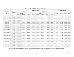
Страница 11: ... 60 A 100 PSIG 1 20 USGPH F6 2 in BFL 130 AF65YB 1 10 70 A 100 PSIG 1 10 USGPH F6 2 in BFL 145 AF65YB 1 20 60 A 100 PSIG 1 20 USGPH F6 2 in BCL 170 AF81WF 1 50 70 B 100 PSIG 1 50 USGPH F16 2 in BCL 190 AF81WF 1 65 70 B 100 PSIG 1 65 USGPH F16 2 in BCL 200 AF81WF 1 75 70 B 100 PSIG 1 75 USGPH F16 2 in BCL 225 AF81WF 2 00 70 B 100 PSIG 2 00 USGPH F16 2 in 1 Head shielded by ceramic insulator 2 Low F...

Страница 12: ...B2U AFII 150 0 90 60 A 145 PSIG 1 00 USGPH FB3 TABLE A 4 WAYNE HSR OIL BURNER SET UP FOR BCL S AND BFL Wayne HSR Series Oil Burners for use with chimney vented units Furnace Model Burner Model Nozzle Pump Pressure Flow Rate Head Off Cycle Damper Setting BCL 80 S W HSR 0 65 80 A 100 PSIG 0 65 USGPH 1 1 BCL 90 S W HSR 0 75 80 A 100 PSIG 0 75 USGPH 1 1 BCL 100 S W HSR 0 85 80 A 100 PSIG 0 85 USGPH 1 ...

Страница 13: ... 5 BFL 130 RF 40F 5 1 00 60 W 145 PSIG 1 10 USGPH 4 3 2 0 BFL 145 RF 40F 5 1 10 60 W 120 PSIG 1 20 USGPH 5 9 2 5 TABLE A 6 RIELLO R35 OIL BURNER SET UP FOR BCL S AND BFL Riello R35 Series Oil Burners for use with chimney vented units Furnace Model Burner Model Nozzle Pump Pressure Flow Rate Air Gate Turbulator Setting BCL 80 S RR R35 3 0 60 60 W 150 PSIG 0 65 USGPH 1 5 0 5 BCL 90 S RR R35 3 0 65 6...

Страница 14: ...e proper setting Riello 40 Series Chimney Vented Riello burners are factory set with respect to pump pressure air gate and turbulator adjustments each model and firing rate must be adjusted accordingly see Appendix A Tables A 4 to A 6 The combustion air can be adjusted by first removing the burner cover and loosening the fixing screws that secures the air adjustment plate Move the adjusting plate ...

Страница 15: ...rature rise is the difference between the furnace outlet temperature and furnace inlet temperature as measured in the vicinity of the connection between the plenum take offs and the trunk ducts Typical temperature rise values range between 65 F and 85 F Perform a smoke spot test The smoke spot should not exceed No 1 on the Bacharach Scale After the air adjustments have been completed re check the ...

Страница 16: ...T DCT12 11 Low 1 HP Low 1 HP 3 5 1 HP 1300 2000 BCL 100 S U G10 DD DD10 10A Med High 1 2 HP Med High 1 2 HP 3 4 1 2 HP 1000 1600 BCL 100 S U T DD12 11T DCT12 11 Low 1 HP Low 1 HP 3 5 1 HP 1300 2000 BCL 120 S U G10 DD DD10 10A High 1 2 HP High 1 2 HP 3 4 1 2 HP 1000 1600 BCL 120 S U T DD12 11T DCT12 11 Medium 1 HP Medium 1 HP 3 5 1 HP 1300 2000 BCL 130 S G10 DD DD10 10A High 1 2 HP High 1 2 HP 3 4 ...

Страница 17: ...FL 100 U G10 DD DD10 10A Med High 1 2 HP Med High 1 2 HP 3 4 1 2 HP 1000 1600 BFL 100 U T DD12 11T DCT12 11 Low 1 HP Low 1 HP 3 5 1 HP 1300 2000 BFL 120 U G10 DD DD10 10A High 1 2 HP High 1 2 HP 3 4 1 2 HP 1000 1600 BFL 120 U T DD12 11T DCT12 11 Medium 1 HP Medium 1 HP 3 5 1 HP 1300 2000 BFL 130 G10 DD DD10 10A High 1 2 HP High 1 2 HP 3 4 1 2 HP 1000 1600 BFL 130 T DD12 11T DCT12 11 Medium 1 HP Me...

Страница 18: ...ons Motor CFM Range 10 10A 3 x BCL 80 S U G10 3 x 7 x 4L420 1 2 HP 3 x 6 x 4L410 1 2 HP 3 4 1 2 HP 1000 1600 10 10A 3 x BCL 90 S U G10 3 x 7 x 4L420 1 2 HP 3 x 6 x 4L410 1 2 HP 3 4 1 2 HP 1000 1600 10 10A 3 x BCL 100 S U G10 3 x 7 x 4L420 1 2 HP 3 x 6 x 4L410 1 2 HP 3 4 1 2 HP 1000 1600 10 10A 3 x BCL 120 S U G10 3 x 7 x 4L420 1 2 HP 3 x 6 x 4L410 1 2 HP 3 4 1 2 HP 1000 1600 continued on next page...

Страница 19: ... 3 x 5 8 6 x 4L410 1 HP 3 x 5 8 6 x 4L410 1 HP 3 5 1 HP 1600 2200 BCL 225 G12 3 x 5 8 6 x 4L410 1 HP 3 x 5 8 6 x 4L410 1 HP 3 5 1 HP 1600 2200 10 10A 3 x BFL 80 U G10 3 x 7 x 4L420 1 2 HP 3 x 6 x 4L410 1 2 HP 3 4 1 2 HP 1000 1600 10 10A 3 x BFL 90 U G10 3 x 7 x 4L420 1 2 HP 3 x 6 x 4L410 1 2 HP 3 4 1 2 HP 1000 1600 10 10A 3 x BFL 100 U G10 3 x 7 x 4L420 1 2 HP 3 x 6 x 4L410 1 2 HP 3 4 1 2 HP 1000 ...

Страница 20: ...six 2 inch bricks under bottom panel if installing on wood floor 3 Note Purpose of the 18 side clearance is to allow a passageway from the front to the back of the furnace TIP Consider greater clearances front and back for easier servicing TABLE A 11 GENERAL DIMENSIONS INCHES Cabinet Plenum Openings Flue Filter Furnace Model Width Depth Height Supply Gap Return Diameter Height Type Size Shipping W...

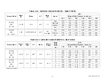
Страница 21: ... 1604 BCL S BFL 80 145 T 1 HP DCT1220 1104 5 85 F 12 3 14 0 MAX Low 1410 1410 1410 1390 1374 1326 TABLE A 13 AIRFLOW CHARACTERISTICS BELT DRIVE CFM External Static Pressure Inches w c Furnace Model Motor HP Motor FLA T Blower Blower Pulley Motor Pulley Turns Out 0 20 0 25 0 30 0 40 0 50 0 60 0 1425 1355 1280 1125 905 516 2 1280 1200 1125 915 555 256 4 1115 1020 905 530 225 11 BCL S 80 120 BFL 80 1...

Страница 22: ...2 1580 1525 1450 1305 1155 959 4 1380 1315 1245 1055 825 460 BCL S 80 145 BFL 80 145 3 4 HP 10 4 85 F G10 5 x 6 1205 1125 1020 775 365 71 0 2274 2177 2080 1847 1532 1099 2 2107 2017 1927 1712 1420 1019 4 1939 1857 1775 1576 1308 939 BCL 170 190 3 4 HP 13 0 85 F G12 7 x 6 1772 1697 1622 1441 1196 859 2 2601 2525 2449 2334 2164 2007 3 2549 2474 2399 2288 2120 1967 4 2497 2424 2350 2241 2077 1927 BCL...

Страница 23: ...28141 Rev A 10 27 06 23 TABLE B 1 BECKETT AND RIELLO CHIMNEY VENTED WIRING DIAGRAM BCL S BFL ...

Страница 24: ...28141 Rev A 10 27 06 24 TABLE B 2 BECKETT AND RIELLO DIRECT VENT WIRING DIAGRAM BCL S BFL ...

Страница 25: ...internal wiring connections loose connectors etc No fuel oil Check fuel oil supply Check that all hand operated all fuel oil valves are in the open position Fill oil storage tank if necessary Clogged nozzle Replace nozzle with high quality replacement Use rating plate or Tables in Appendix A as a guide Clogged oil filter Replace oil tank filter or in line filter if used Low oil pump pressure Conne...

Страница 26: ...re increased diameter Electrodes out of adjustment or defective Check electrode settings Check electrodes for dirt build up or cracks in porcelain Poor transformer high voltage connections or defective transformer Check contacts between transformer and electrodes If OK replace transformer Fuel oil filter clogged Replace fuel oil storage tank filter and or fuel oil in line filter Defective oil pump...

Страница 27: ...ion Check thermostat heat anticipator setting against measured amperage draw Increase heat anticipator setting if necessary If the thermostat is being influenced by drafts sunlight duct work etc relocate to more suitable location Insufficient air flow Check all dampers Open closed dampers including registers in unused rooms Check system temperature rise If temperature rise is too high speed up blo...

Страница 28: ... the pre purge The hot vent can be checked with a lit taper for signs of air movement around joints or seams Ensure that all safety devices and electrical components have been set for normal operation Ensure that all electrical connections are tight and that the wiring is secure IMPORTANT Please ensure that the homeowner is informed and understands 1 where the circuit breaker or fuse is located in...

Страница 29: ...29809 Rev A 10 19 2006 29 ...

Страница 30: ...re Retainer Channel 27510 20 Blower Access Door 29053L Door Handle P2 41 28673 21 Front Panel Baffle 3022140A 22 Top Front Panel Baffle 29223 23 Oil Burner assembly Beckett AF81WF 29597 Burner Motor 1 7 HP 3450 RPM PSC 29689 Beckett Cleancut Oil Pump A2EA6520 29688 Solid State Ignitor FRANCE 10SAY 04 29522 Primary Combustion Control R7184B 29664 Air Tube Combination AF81WF 29530 Flame Retention He...

Страница 31: ...X 3 4 2240008 Fan Belt 4L430 2240022 Blower Base Feet LH 8173B2 Blower Base Feet RH 8173B1 Blower Base Feet Rubber Grommet 4 required 26415 34 Blower Assembly BCL 200 225 29217 Blower Housing and Wheel G12 With Ball Bearings 29222 Blower Motor 1 hp Single Speed 29218 Motor Pulley 3 1 2 X 5 8 Adjustable With Keyway 19779 Blower Pulley 6 X 3 4 2240006 Fan Belt 4L410 2240020 Blower Base Feet LH 8173B...

Страница 32: ...29809 Rev A 10 19 2006 32 ...

Страница 33: ...et 2 per unit 21994 21994 20 Cleanout Pipe Cover 2 per unit 29162 29162 Cleanout Cap Gasket 2 per unit 240006333 240006333 21 Clean out Gasket Retainer 2 per unit 29161 29161 Cleanout Gasket 2 per unit 29163 29163 22 Air Filter 20 x 25 x 1 Permanent 2180024 2180024 23 Junction Box 21318 21318 24 Wire Harness Blower Direct Drive 27273 27273 Wire Harness Blower Belt Drive 27272 27272 25 Wire Harness...

Страница 34: ...lower Motor 1 2 hp 4 Speed 26088 26088 Motor Mounting Band TR5868 17811 17811 Motor Mount Arms 10 10 DD Blower 3 per unit 26251 26251 Motor Run Capacitor 10 mfd 370 vac 27743 27743 Capacitor Strap 27760 27760 Capacitor Insulator 27769 27769 Blower Base Feet LH 29703 29703 Blower Base Feet RH 29704 29704 Blower Base Feet Rubber Grommet 4 required 26415 26415 32 Blower Assembly Complete Belt Drive 6...

Страница 35: ...Run Capacitor 20 mfd 370 vac 27745 27745 Capacitor Strap 27761 27761 Capacitor Insulator 27768 27768 Blower Base Feet LH 26013 26013 Blower Base Feet RH 26012 26012 Terminal Block EE8 201 26833 26833 Blower Base Feet Rubber Grommet 4 required 26415 26415 PARTS LISTING LOWBOY MODEL BCL 100SB2U Ref No Description BCL 100SB2U Part No All parts are the same as listed on the previous pages for Model BC...

Страница 36: ...29809 Rev A 10 19 2006 36 ...

Страница 37: ...asket 2 per unit 21994 21994 20 Cleanout Pipe Cover 2 per unit 29162 29162 Cleanout Cap Gasket 2 per unit 240006333 240006333 21 Clean out Gasket Retainer 2 per unit 29161 29161 Cleanout Gasket 2 per unit 29163 29163 22 Air Filter 20 x 25 x 1 Permanent 2180024 2180024 23 Junction Box 21318 21318 24 Wire Harness Blower Direct Drive 27273 27273 Wire Harness Blower Belt Drive 27272 27272 25 Wire Harn...

Страница 38: ...eed 26088 26088 Motor Mounting Band TR5868 17811 17811 Motor Mount Arms 10 10 DD Blower 3 per unit 26251 26251 Motor Run Capacitor 10 mfd 370 vac 27743 27743 Capacitor Strap 27760 27760 Capacitor Insulator 27769 27769 Blower Base Feet LH 29703 29703 Blower Base Feet RH 29704 29704 Blower Base Feet Rubber Grommet 4 required 26415 26415 32 Blower Assembly Complete Belt Drive 6033C6 6033C7 Blower Hou...

Страница 39: ...vac 27745 27745 Capacitor Strap 27761 27761 Capacitor Insulator 27768 27768 Blower Base Feet LH 26013 26013 Blower Base Feet RH 26012 26012 Terminal Block EE8 201 26833 26833 Blower Base Feet Rubber Grommet 4 required 26415 26415 PARTS LISTING LOWBOY MODEL BFL 100B2U Ref No Description BFL 100B2U Part No All parts are the same as listed on the previous pages for Model BFL 120 145 except where note...

Страница 40: ...Model No Serial No Date Installed Contractor Contact Address Postal Code Telephone No After Hours No If different from Installation Contractor Service Tech Telephone No After Hours No Fuel Supplier Fuel Oil Supplier Contact Telephone No After Hours No ...

Страница 41: ...28141 Rev A 10 27 06 NOTES ...

Страница 42: ...28141 Rev A 10 27 06 ...

Страница 43: ...28141 Rev A 10 27 06 ...

Страница 44: ...laceburg Ontario N8A 5E5 Can Tel 519 627 0791 Fax 519 627 4719 2201 Dwyer Avenue Utica New York 13504 USA Tel 315 797 1310 Fax 315 724 9319 85 Middle Road Dunkirk New York 14048 USA Tel 716 366 5500 Fax 716 366 1209 www ecrinternational com ...

Отзывы: