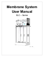
ELC
– Series User Manual
MKTF
– 506-A
9
03/18
ELECTRICAL
The motor used on the ELC is available in 110 VAC 60 Hertz 1 Phase. Each ELC
– Series system is
equipped with an eight
–foot electrical cord with a three pronged electrical plug.
Ensure that the electrical circuit supplying the system is compatible with the requirements of the specific
ELC
– Series model you are installing.
IT IS RECOMMENDED THAT A LICENSED ELECTRICIAN WIRE YOUR SYSTEM IN
ACCORDANCE WITH LOCAL AND NATIONAL ELECTRICAL CODES (NEC).
TO REDUCE THE RISK OF ELECTRICAL SHOCK, THE INCOMING POWER
SUPPLY MUST INCLUDE A PROTECTIVE EARTH GROUND.
ELC
– Series systems are not typically controlled with a liquid level switch in a storage tank. The liquid
level switch turns the system on when the water level in the tank drops, and off when the tank is full.
Should you choose a liquid switch(s) for your application it can be obtained by your local dealer or
distributor. If a liquid level switch is to be used, install it at this time.
PRE
–FILTRATION
ELC
– Series systems are supplied with a 5–micron sediment filter and a 10 micron carbon block filter
(ELC
– 750 only). Change the cartridge once a month or when a 10–15 psi differential exists between
the two pre
–filter gauges.
THE SYSTEM MUST BE OPERATED ON FILTERED WATER ONLY.
PUMP
The pump type used on the ELC
– Series systems is rotary vein pump. If any damage occurs to your
system’s pump, a re–build kit may be available. Contact your local dealer or distributor and inform
them of your system and pump model.
MOUNTING
The free standing system should be bolted down or securely fastened in compliance with local
regulation standards.
Содержание ELC-1500
Страница 1: ...Membrane System User Manual ELC Series ELC 1500 w...
Страница 2: ...ELC Series User Manual MKTF 506 A 2 03 18 This page intentionally left blank...
Страница 11: ...ELC Series User Manual MKTF 506 A 11 03 18 SYSTEM IDENTIFICATION Figure 1...
Страница 15: ...ELC Series User Manual MKTF 506 A 15 03 18 Figure 2...
Страница 16: ...ELC Series User Manual MKTF 506 A 16 03 18 Figure 3...
Страница 26: ...ELC Series User Manual MKTF 506 A 26 03 18 OPERATING LOG...
Страница 30: ...ELC Series User Manual MKTF 506 A 30 03 18 ELC 750 FLOW DIAGRAM...
Страница 31: ...ELC Series User Manual MKTF 506 A 31 03 18 ELC 1500 FLOW DIAGRAM...
Страница 32: ...ELC Series User Manual MKTF 506 A 32 03 18 ELC SERIES ELECTRICAL SCHEMATIC...


