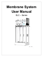
ELC
– Series User Manual
MKTF
– 506-A
14
03/18
REPLACING THE MEMBRANE ELEMENT:
THE BRINE SEAL MUST BE IN THE CORRECT POSITION FOR EACH MEMBRANE
ELEMENT HOUSING. THE BRINE SEAL IS A RUBBER SEAL THAT PROTRUDES ON ONE
SIDE OF THE MEMBRANE AND IS ALWAYS ON THE FEED SIDE OF THE MEMBRANE
ELEMENT. FOR ELC
– SERIES REVERSE OSMOSIS SYSTEMS THE BRINE SEAL
SHOULD BE ON THE TOP SIDE OF THE MEMBRANE HOUSINGS.
1. Disconnect the tubing from the bottom of the membrane housing. Unscrew the
membrane housing from the system.
2. Remove one membrane element at a time from the pressure vessels, from the
top of each housing. Long nose pliers may be necessary to pull the old
membrane element out of the membrane element housing.
3. Lubricate the brine seal and o
–rings with a non
–
petroleum based lubricant, such
as Dow Corning
®
111. Do not use a petroleum
–
based lubricant.
4. Install membranes with brine seal location depicted in Figure 2, on Page 15 for
ELC
– 1500 or Figure 3, page 16, for ELC – 750.
5. With a smooth and constant motion, push the membrane element into the
housing.
6. Screw the membrane housing back onto the system and reattach the tubing.
7. Reconnect any fittings that may have been disconnected when the membrane
pressure vessels were disassembled.
8. To start
–
up the system, please refer to the Initial Start
–
Up section of this User
Manual.
THE MEMBRANES MUST BE FLUSHED FOR AT LEAST 30 MINUTES TO
REMOVE THE PRESERVATIVE FROM THE MEMBRANE. DISCARD ALL OF THE
PERMEATE, WHICH IS PRODUCED DURING THE FLUSH PERIOD.
Содержание ELC-1500
Страница 1: ...Membrane System User Manual ELC Series ELC 1500 w...
Страница 2: ...ELC Series User Manual MKTF 506 A 2 03 18 This page intentionally left blank...
Страница 11: ...ELC Series User Manual MKTF 506 A 11 03 18 SYSTEM IDENTIFICATION Figure 1...
Страница 15: ...ELC Series User Manual MKTF 506 A 15 03 18 Figure 2...
Страница 16: ...ELC Series User Manual MKTF 506 A 16 03 18 Figure 3...
Страница 26: ...ELC Series User Manual MKTF 506 A 26 03 18 OPERATING LOG...
Страница 30: ...ELC Series User Manual MKTF 506 A 30 03 18 ELC 750 FLOW DIAGRAM...
Страница 31: ...ELC Series User Manual MKTF 506 A 31 03 18 ELC 1500 FLOW DIAGRAM...
Страница 32: ...ELC Series User Manual MKTF 506 A 32 03 18 ELC SERIES ELECTRICAL SCHEMATIC...


