


06.11.2018 Rev. 08
21
8.
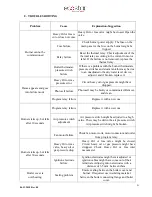
TROUBLESHOOTING
Problem
Cause
Explanation-Suggestion
Burner cannot be
commissioned
Heavy Oil or Gas is
cut or does not come
Heavy Oil or Gas valve might be closed. Open the
valve.
Fuse failure
Check burner power supply. The fuse on the
main panel or the fuse on the burner might be
tripped.
Relay failure
Reset the thermal relay. Check adjustment of the
thermal relay according to the current in motor
label. If the failure is not removed, replace the
thermal relay.
Boiler thermostat,
pressure switch
failure
If there is a problem with the burner thermostats,
pressure switches and steam tank this may be due
to an unadjusted or faulty water level device;
adjust it and if broken, replace it.
Flame appears and goes
into failure mode.
Heavy Oil or Gas
pressure error
Circuit heavy oil or gas pressure might have
dropped.
Photocell failure
Photocell may be faulty or contaminated. Remove
and clean..
Program relay failure
Replace it with a new one.
Burner starts up, but fails
after 10 seconds.
Program relay failure
Replace it with a new one.
Air pressure switch
adjustment
Air pressure switch might be adjusted to a high
value. There may be dirt in the air pressure switch.
Air pressure switch might be broken.
Fan motor failure
Check fan motor coils, motor contactor and outlet
from program relay.
Burner starts up, but fails
after 30 seconds.
Heavy Oil or Gas
valve, heavy oil or
gas pressure drop
Heavy Oil or Gas valve might be closed.
Circuit heavy oil or gas pressure might have
dropped. Check Heavy Oil or Gas inlet
manometer.
Ignition electrode
failure
Ignition electrodes might be misadjusted or
ignition cables might have come out of their
terminals. Adjust ignition electrodes with a
distance of 3-5 mm. between them.
Boiler cover is
overheating.
Sealing problem
Ensure sealing between the boiler cover and
burner. If required, use insulating material
between the boiler connecting flange and boiler
cover.
Содержание ECO 300
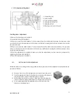
Страница 11: ...06 11 2018 Rev 08 10 4 2 Burner Dimensions...
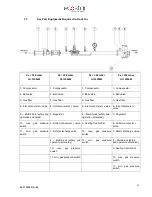
Страница 16: ...06 11 2018 Rev 08 15 HA D Nozzle Hydraulic Diagram...


