06.11.2018 Rev. 08
16
Ø
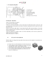
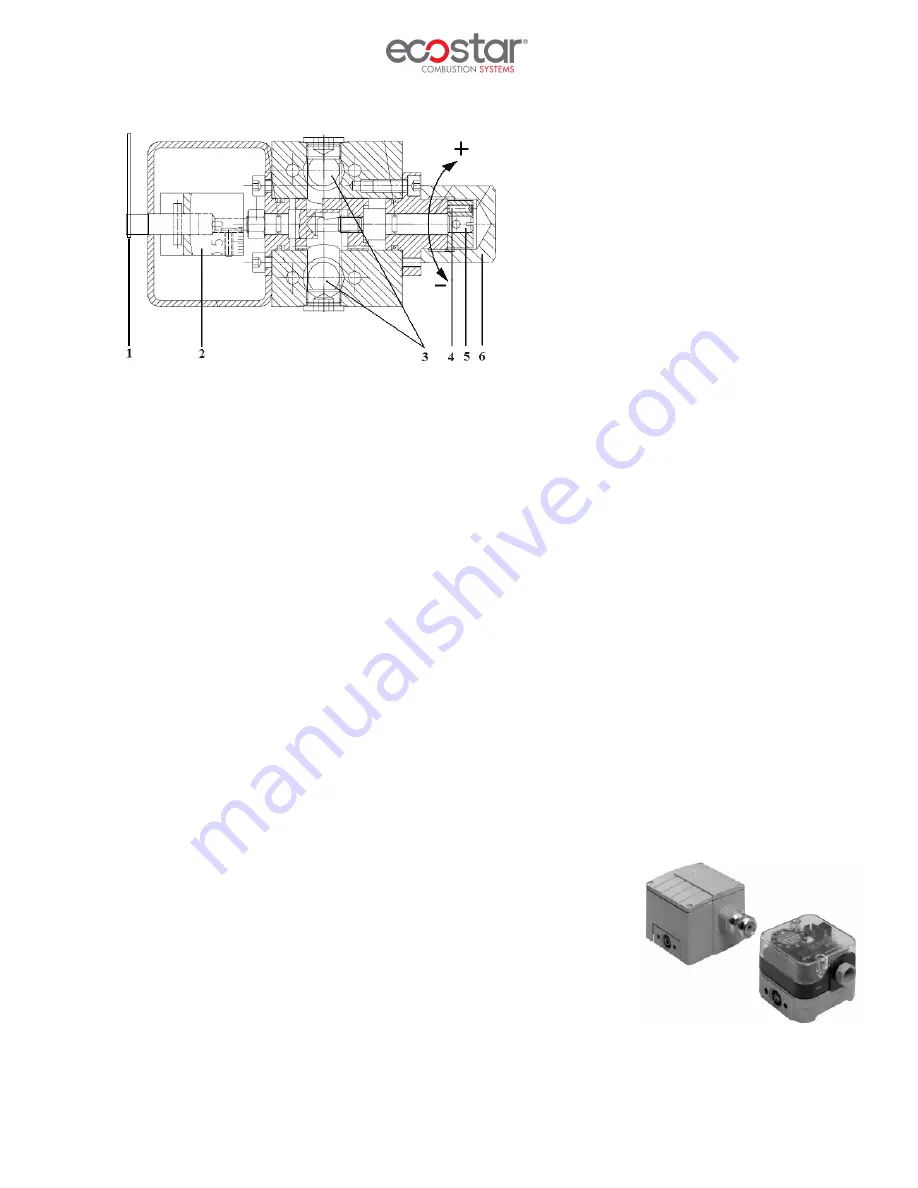
Oil Adjustment Regulator
1- Connecting rod
2- Scale coupler
3- Fuel connection points
4- Adjustment fixing bolt
5- Adjustment bolt
6- Housing cover (screw hood)
Fuel Regulator Adjustment
1-Remove the housing cover number 6
2-Loosen the fixing bolt number 4
3-When you rotate the shaft number 5 (when looked from the shaft end) clockwise, the pressure value
you observe from return manometer will increase, and burner consumption will also increase since nozzle
pressure increases.
4-When you rotate the shaft number 5 (when looked from the shaft end) anti-clockwise, the pressure
value you observe from return manometer will decrease, and burner consumption will also decrease since
nozzle pressure decreases.
5-When the adjustment is completed; make sure that the adjustment you have made is permanent by
tightening the fixing bolt number 4.
6-Place the housing cover number 6.
6.3.
Air Pressure Switch Adjustment
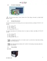
While the burner is working without any problem, the air pressure switch is adjusted to desired minimum
pressure as follows.
Ø
Unscrew the screw of the transparent cover and remove the cover.
Ø
Turn the adjustment wheel in the direction to increase the pressure,
note the pressure value at which the burner is failed.
Ø
Set the pressure switch to a value 1 mbar lower than the pressure
value at which the burner failed and close the pressure switch lid.
Ø
It is recommended that this adjustment is carried out when the
burner is at minimum load.
Содержание ECO 300
Страница 11: ...06 11 2018 Rev 08 10 4 2 Burner Dimensions...
Страница 16: ...06 11 2018 Rev 08 15 HA D Nozzle Hydraulic Diagram...


