10 |
P a g e
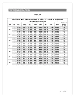
ES90LVP ECM blower performance (CFM/amps)
SWITCH
SETTING
0.1” WC
0.2” WC
0.3”
WC
0.4”
WC
0.5”
WC
600 CFM
603
0.82
607
1.02
610
1.25
618
1.49
620
1.7
700 CFM
681
1.04
688
1.26
699
1.47
702
1.76
708
1.99
800 CFM
756
1.22
782
1.58
800
1.92
823
2.28
844
2.58
900 CFM
874
1.7
894
2.08
918
2.44
927
2.82
940
3.11
1000 CFM
1000
2.31
1022
2.76
1034
3.14
1045
3.53
1060
3.89
1100 CFM
1120
3.07
1133
3.5
1145
3.93
1153
4.38
1170
4.8
1200 CFM
1195
3.56
1205
4.07
1211
4.5
1223
4.9
1228
5.38
1300 CFM
1282
4.32
1286
4.74
1295
5.2
1305
5.73
1312
6.17
QUICK
START-UP
PROCEDURES
Refer to the superseding installation instructions before following the start-up procedures.
1.
Fill the system with water. Do not start the system.
2.
Purge all air from the system. Isolation and purge valves are strongly recommended.
3.
Purge all air from the space heating loop by closing the isolation valve on the return leg
of the loop and open the drain to purge air. Open the return leg isolation valve and
then close the drain valve.
4.
Start the hot water generating equipment
per the manufacturer’s recommendations.
Set the design water temperature to deliver the necessary amount of BTUs to the air
handler.
Содержание ES50LVP
Страница 16: ...15 P a g e PIPING DIAGRAMS Tankless Water Heater Piping ...
Страница 17: ...16 P a g e Combi Boiler Piping ...
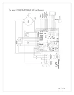
Страница 20: ...19 P a g e Ecosmart ES50LVP ES90LVP Wiring Diagram ...


