23 |
P a g e
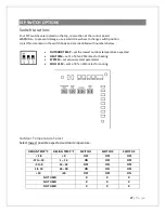
(1)
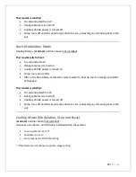
Test Mode - heat source is brought on, fan runs at HEAT CFM setting and pump runs at full
speed irrespective of thermostat setting. Useful for eliminating air in the system during
installation.
(2)
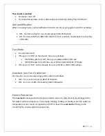
Normal Fan Cooling runs at rate set by COOL CFM switch.
Dehumidification Fan Cooling runs at 85% of COOL CFM rate for 10 min. and then reverts back
to rate set by COOL CFM.
(3)
Normal Continuous Fan runs at rate set by HEAT CFM switch.
Low speed Continuous Fan runs at 50% of rate set by HEAT CFM switch.
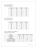
Cool CFM (ES90LVP)
CFM
@ 0.5”
WC
SWITCH 1
SWITCH 2
SWITCH 3
600
OFF
OFF
OFF
700
ON
OFF
OFF
800
OFF
ON
OFF
900
ON
ON
OFF
1000
OFF
OFF
ON
1100
ON
OFF
ON
1200
OFF
ON
ON
1300
ON
ON
ON
Cool CFM (ES50LVP)
CFM
@ 0.5” WC
SWITCH 1
SWITCH 2
SWITCH 3
300
OFF
OFF
OFF
400
ON
OFF
OFF
500
OFF
ON
OFF
600
ON
ON
OFF
700
OFF
OFF
ON
800
ON
OFF
ON
900
OFF
ON
ON
Содержание ES50LVP
Страница 16: ...15 P a g e PIPING DIAGRAMS Tankless Water Heater Piping ...
Страница 17: ...16 P a g e Combi Boiler Piping ...
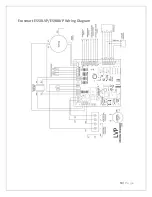
Страница 20: ...19 P a g e Ecosmart ES50LVP ES90LVP Wiring Diagram ...


