background image

AR2…SE.. Instructions 

                                                         Form 120127 


4 ELECTRIC 

CONNECTIONS 


4.1


After having installed the AR gear motor and before fastening it mechanically to 
the device to be controlled, proceed with wiring and earthling. 


4.2


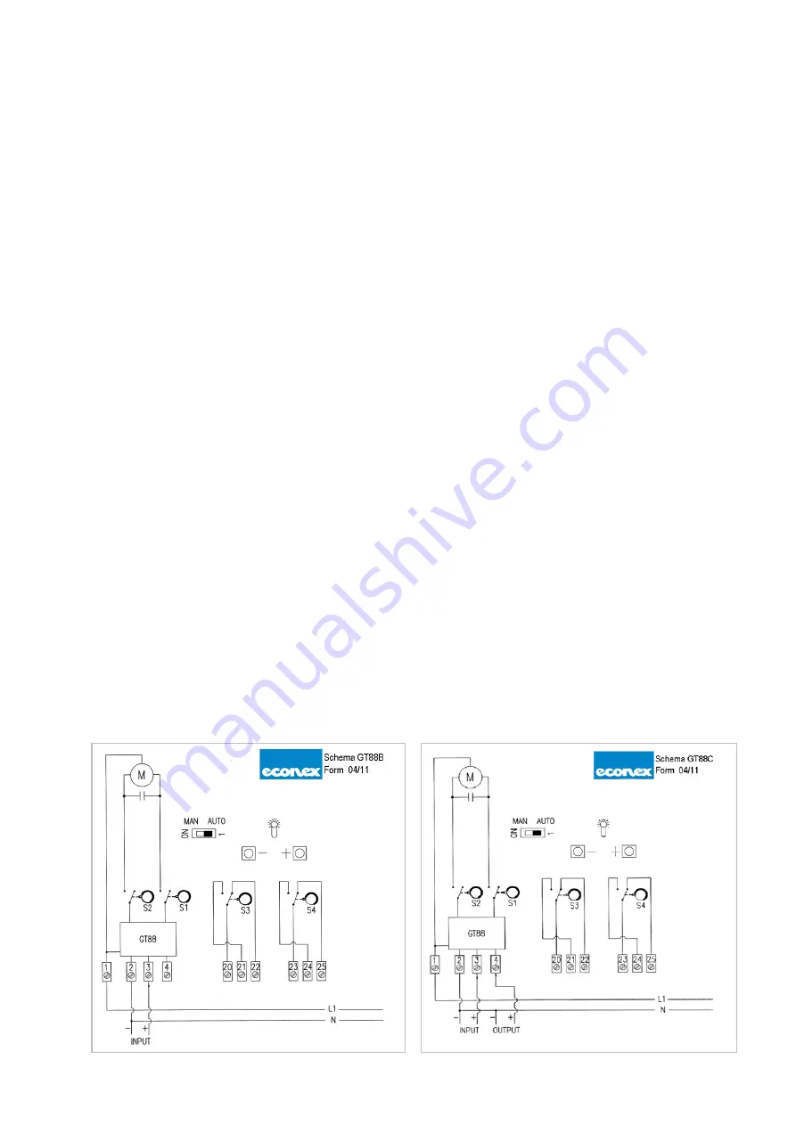
The wiring diagrams are reported both in the attached technical bulletin and on the 
plate inside the cover. 


4.3


Warning: before servicing make sure that power supply is disconnected by means 
of the two-pole-switch [phase and neutral]. In case of non-observance, damages 
to people and to the equipment may occur. 


4.4


External supply voltage transformer with load 

>

 15 VA protected against overloading. 


4.5


To accede to the internal wiring terminal board remove the cover by loosening the 
4 fastening screws. 


4.6


On the frame of the AR gear motor are located 2 threaded holes for the fitting of 
the conduit plug PG 13.5 and 2 extra ¼” holes [on request] if pressurizing of the 
motor is requested. 


4.7 

All wires must comply with local prescriptions and, in any case, their section must 
be ranging between 1 and 1.5 mm².  


4.8


Connection piping recommended HO7V-U…G 1.5 mm². 


4.9 

The wiring diagrams show the AR2...E gear motor at end position closed [0°]. 


W

ARNING


An immediate accident may occur onto circuit board due to wrong wiring. 

 Check 

it 

carefully

 before servicing. 


4.10 

The auxiliary microswitches are single-pole double through and are voltage-free. 


4.11 

The auxiliary microswitches rating is 0,5 A / 48 Vdc e Vac. 


4.12 

Make sure that power supply and system frequency match to the values indicated 
on the AR gear motor’s plate. 


W

ARNING


Transformer power supply must be separated from that of the gear motor. 


4.13 

The low-tension signalling cables [tension lower than 48V] must be laid separately 
from the higher-tension-conduits [tension higher than 48V]. In case they are laid in 
a single channel, screened cables must be used. 


Valid only for AR2…SE1, SE2, SE7 e SE8 


Содержание AR2 SE Series

Страница 1: ...NANCE AND CHECKS 7 8 1 MAINTENANCE 7 8 2 CHECKS 8 9 REPLACEMENT 8 10 ELECTRONIC CONFIGURATION 8 10 1 ELECTRONIC CONFIGURATION AR2 SE1 INPUT SIGNAL 0 10V OUTPUT SIGNAL 0 10V 9 10 2 ELECTRONIC CONFIGURATION AR2 SE2 INPUT SIGNAL 4 20 MA OR 0 10V OUTPUTSIGNAL 0 10V 10 10 3 ELECTRONIC CONFIGURATION AR2 SE4 INPUT SIGNAL 0 10V 11 10 4 ELECTRONIC CONFIGURATION AR2 SE5 INPUT SIGNAL 4 20 MA 12 10 5 ELECTRON...

Страница 2: ... motor are indicated on the label All technical functions are specified in the relative technical data sheet 1 7 Before installing or operating the AR gear motor make sure that its employment complies with the range of performances reported on the label 1 8 When positioning the gear motor consider that it must be easily accessible in order to be able to perform wiring and adjustment of endswitches...

Страница 3: ...odel refer to 10 Local control station Auto Manual and Open Close Stop Rating of el contacts limit and auxiliary switches 0 5 A 48 Vdc and Vac Enclosure Rating IP 54 according to IEC 529 Duty cycle continuous 100 Conduit knockouts 2 x Pg 13 5 3 INSTALLATION 3 1 The AR gear motor must be positioned so that the square shaft POWER END is turned towards the device to be put in motion 3 2 If no other a...

Страница 4: ...nd 2 extra holes on request if pressurizing of the motor is requested 4 7 All wires must comply with local prescriptions and in any case their section must be ranging between 1 and 1 5 mm 4 8 Connection piping recommended HO7V U G 1 5 mm 4 9 The wiring diagrams show the AR2 E gear motor at end position closed 0 WARNING An immediate accident may occur onto circuit board due to wrong wiring Check it...

Страница 5: ... right side introducing the pin into one of the holes on the sides of the blue cam S3 or S4 according to the need and lift it to required angle position Picture 2 5 2 4 By the blue cam in the rearmost position at first use the lever on its curved side to move the blue cam to a more suitable position to perform adjustment 5 2 5 Cam adjustment is possible in both directions and along the whole rotat...

Страница 6: ...the right handside up to 45 Then the actuator will rotate by 45 between 45 and 0 with the entire signal 4 20 mA or 0 10V with rotation counter clockwise dip switch no 1 on the left handside up to 90 Then the actuator will rotate by 45 between 90 up to 45 with the entire signal 4 20 mA or 0 10V 3 In order to widen the working range it is possible to set any degree of angle between 45 and 90 with a ...

Страница 7: ...ll adjustments are already set at factory Hence it is recommended to avoid any intervention on cams and potentiometer 7 2 Warning potentiometer is installed for card balancing purposes ONLY Consequently it is not to be used 8 MAINTENANCE AND CHECKS 8 1 MAINTENANCE 8 1 1 AR2 gear motor does not require any particular current maintenance 8 1 2 AR2 gear motor does not require any lubrication since th...

Страница 8: ...pply from the AR2 E motor remove the gear motor s cover disconnect electric wiring remove the levers between the AR2 E gear motor and the controlled device install the new gear motor proceeding as per instructions given in the foregoing chapters 10 ELECTRONIC CONFIGURATION The digital electronic board mounted on AR2 gear actuator enable to set various features options like rotation direction resol...

Страница 9: ...ignal 0 10 V d c N A 6 Impedance at 4400 Ohm only for Input Signal 0 10V Impedance at 250 Ohm only for Input Signal 0 10V For other setting please look here below 3 4 OFF ON STANDARD setting Input and Output signal always aligned For example 2V input e 2V output 3 4 OFF ON REVERSE OUTPUT only for counter clockwise rotation For example 2V Input signal and 8V Output Signal 3 4 OFF ON DS 3 turned ON ...

Страница 10: ...mA DS 6 MUST be turned ON 6 Impedance at 4400 Ohm only for Input Signal 0 10V Always turned ON with Input Signal 4 20 mA Impedance at 250 Ohm only for Input Signal 0 10V For other setting please look here below 3 4 OFF ON STANDARD setting Input and Output signal always aligned For example 2V input e 2V output 3 4 OFF ON REVERSE OUTPUT only for counter clockwise rotation For example 2V Input signal...

Страница 11: ...ion 200 steps 3 4 Please refer to the below reported scheme 5 Input Signal 0 10 V N A 6 Impedance at 4400 Ohm only for Input Signal 0 10V Impedance at 250 Ohm only for Input Signal 0 10V For special setting please look here below 3 4 OFF ON DS 3 turned ON and DS 4 turned OFF Actuator rotates for 90 with Mid Low Input Signal For example 0 5V with rotation of 90 3 4 OFF ON DS 3 turned OFF and DS 4 t...

Страница 12: ... Resolution 125 steps High Resolution 200 steps 3 4 Please refer to the below reported scheme 5 N A Input Signal 4 20 mA 6 N A DS 6 MUST be turned ON For special setting please look here below 3 4 OFF ON DS 3 turned ON and DS 4 turned OFF Actuator rotates for 90 with Mid Low Input Signal For example 4 12 mA with rotation of 90 3 4 OFF ON DS 3 turned OFF and DS 4 turned ON Actuator rotates for 90 w...

Страница 13: ...PUT and OUTPUT always aligned 5 N A Input Signal 4 20 mA 6 N A DS 6 MUST be turned ON For other setting please look here below 3 4 OFF ON STANDARD setting Input and Output signal always aligned For example 2V input e 2V output 3 4 OFF ON REVERSE OUTPUT only for counter clockwise rotation For example 2V Input signal and 8V Output Signal 3 4 OFF ON DS 3 turned ON and DS 4 turned OFF Actuator rotates...

Страница 14: ...5 N A Input Signal 4 20 mA 6 N A DS 6 MUST be turned ON For other setting please look here below 3 4 OFF ON STANDARD setting Input and Output signal always aligned For example 2V input e 2V output 3 4 OFF ON REVERSE OUTPUT only for counter clockwise rotation For example 2V Input signal and 8V Output Signal 3 4 OFF ON DS 3 turned ON and DS 4 turned OFF Actuator rotates for 90 with Mid Low Input Sig...

Отзывы: